This section deals with the selection of the type of foundation. The selection of a particular type of foundation is often based on a number of factors, such as:
1. Adequate Depth. It must have an adequate depth to prevent frost damage. For such foundations as bridge piers, the depth of the foundation must be sufficient to prevent undermining by scour.
2. Bearing Capacity Failure. The foundation must be safe against a bearing capacity failure.
3. Settlement. The foundation must not settle to such an extent that it damages the structure.
4. Quality. The foundation must be of adequate quality so that it is not subjected to deterioration, such as the sulphate attack of concrete footings.
5. Adequate Strength. The foundation must be designed with sufficient strength that it does not fracture or break apart under the applied superstructure loads. It must also be properly constructed in conformance with the design specifications.
6. Adverse Soil Changes. The foundation must be able to resist long-term adverse soil changes. An example is expansive soil (silts and clays), which could expand or shrink causing movement of the foundation and damage to the structure.
7. Seismic Forces. The foundation must be able to support the structure during an earthquake without excessive settlement or lateral movement.
Shallow Foundations
A shallow foundation is often selected when the structural load will not cause excessive settlement of the underlying soil layers. In general, shallow foundations are more economical to construct than deep foundations. Common types of shallow foundations are listed in Table 6.2 and described below:
1. Spread Footings, Combined Footings, and Strip Footings.
These types of shallow foundations are probably the most common types of building foundations. Examples of these types of footings are shown in Fig. 6.40.
2. Mat Foundation.
Examples of mat foundations are shown in Fig. 6.41. Based on economic considerations, mat foundations are constructed for the following reasons:
(a) Large Individual Footings. A mat foundation is often constructed when the sum of individual footing areas exceeds about one-half of the total foundation area.
(b) Cavities or Compressible Lenses. A mat foundation can be used when the subsurface exploration indicates that there will be unequal settlement caused by small cavities or compressible lenses below the foundation. A mat foundation would tend to span over the small cavities or weak lenses and create a more uniform settlement condition.
(c) Shallow Settlements. A mat foundation can be recommended when shallow settlements predominate, and the mat foundation would minimize differential settlements.
(d) Unequal Distribution of Loads. For some structures, there can be a large difference in building loads acting on different areas of the foundation. Conventional spread footings could be subjected to excessive differential settlement, but a mat foundation would tend to distribute the unequal building loads and reduce the differential settlements.
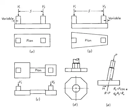
FIGURE 6.40 Examples of shallow foundations: (a) combined footing; (b) combined trapezoidal footing; (c) cantilever or strap footing; (d) octagonal footing; (e) eccentric loaded footing with resultant coincident with area so soil pressure is uniform.
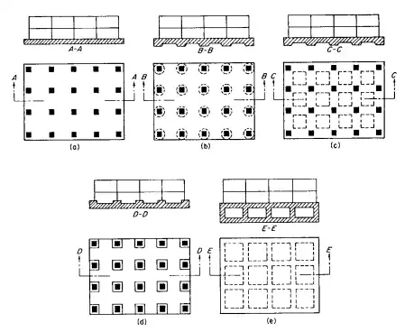
FIGURE 6.41 Examples of mat foundations: (a) Flat plate; (b) plate thickened under columns; (c) beam-and-slab; (d) plate with pedestals; (e) basement walls as part of mat.
(e) Hydrostatic Uplift. When the foundation will be subjected to hydrostatic uplift due to a high groundwater table, a mat foundation could be used to resist the uplift forces.
3. Post-Tensioned Slabs-on-Grade
Post-tensioned slabs-on-grade are common in southern California and other parts of the United States. They are an economical foundation type when there is no ground freezing, or the depth of frost penetration is low. The most common uses of post-tensioned slabs-on-grade are to resist expansive soil forces or when the projected differential settlement exceeds the tolerable value for a conventional (lightly reinforced) slabs-on-grade. For example, post-tensioned slabs-on-grade are frequently recommended if the projected differential settlement is expected to exceed 2 cm (0.75 in). Installation and field inspection procedures for post-tensioned slabs-on-grade have been prepared by the Post-Tensioning Institute (‘‘Design and Construction of Posttensioned Slabs-on-Ground,’’ 2d ed., Phoenix) provides typical anchorage details for the tendons.
4.Shallow Foundation Alternatives.
If the expected settlement for a proposed shallow foundation is too large, then other options for foundation support or soil stabilization must be evaluated. Some commonly used alternatives are as follows:
(a) Grading. Grading operations can be used to remove the compressible soil layer and replace it with structural fill. Usually the grading option is economical only if the compressible soil layer is near the ground surface and the groundwater table is below the compressible soil layer or the groundwater table can be economically lowered.
(b) Surcharge. If the site contains an underlying compressible cohesive soil layer, the site can be surcharged with a fill layer placed at the ground surface. Vertical drains (such as wick drains or sand drains) can be installed in the compressible soil layer to reduce the drainage paths and speed up the consolidation process. Once the compressible cohesive soil layer has had sufficient consolidation, the fill surcharge layer is removed, and the building is constructed.
(c) Densification of Soil. Many different methods can be used to densify loose or soft soil. For example, vibro-flotation and dynamic compaction are often effective at increasing the density of loose sand deposits. Another option is compaction grouting, which consists of intruding a mass of very thick consistency grout into the soil, which both displaces and compacts the loose soil.
(d) Floating Foundation. A floating foundation is a special type of deep foundation where the weight of the structure is balanced by the removal of soil and construction of an underground basement.
Deep Foundations
Probably the most common type of deep foundation is the pile foundation. Table 6.15 presents pile type characteristics and uses. Piles can consist of wood (timber), steel H-sections, precast concrete, cast-in-place concrete, pressure injected concrete, concrete filled steel pipe piles, and composite type piles. Piles are either driven into place or installed in predrilled holes. Piles that are driven into place are generally considered to be low displacement or high displacement, depending on the amount of soil that must be pushed out of the way as the pile is driven. Examples of low displacement piles are steel H-sections and open-ended steel pipe piles that do not form a soil plug at the end. Examples of high-displacement piles are solid section piles, such as round timber piles or square precast concrete piles, and steel pipe piles with a closed end.
A cast-in-place pile is formed by making a hole in the ground and then filling the hole with concrete. As shown in Fig. 6.42, in its simplest form, the cast-in place pile consists of an uncased hole that is filled with concrete. If the soil tends to cave into the hole, then a shell-type pile can be installed (see Fig. 6.42). This consists of driving a steel shell or casing into the ground. The casing may be driven with a mandrel, which is then removed, and the casing is filled with concrete. In other cases, the casing can be driven into place and then slowly removed as the hole is filled with concrete.
Figure 6.43 shows typical pile configurations.
TABLE 6.15 Typical Pile Characteristics and Uses
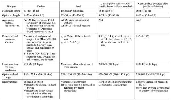
TABLE 6.15 Typical Pile Characteristics and Uses (Continued)
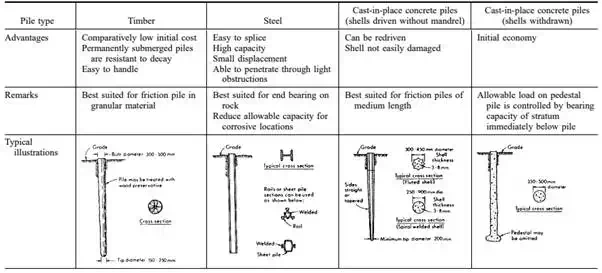
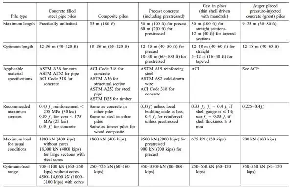
TABLE 6.15 Typical Pile Characteristics and Uses (Continued)
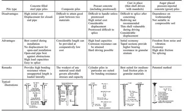
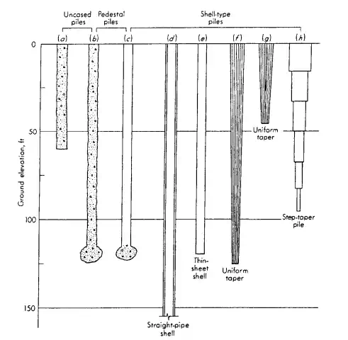
FIGURE 6.42 Common types of cast-in-place concrete piles: (a) Uncased pile; (b) Franki uncased-pedestal pile; (c) Franki cased-pedestal pile; (d) welded or seamless pipe pile; (e) cased pile using a thin sheet shell; (f) monotube pile; (g) uniform tapered pile; (h) step-tapered pile.