A geosynthetic is defined as a planar product manufactured from polymeric material and typically placed in soil to form an integral part of a drainage, reinforcement, or stabilization system. Common types of geosynthetics used during construction are as follows. 6.11.1 Geogrids Figure 6.48 shows a photograph of a geogrid, which contains relatively high strength polymer grids consisting of longitudinal and transverse ribs connected at their intersections. Geogrids have a large and open structure and the openings (i.e., apertures) are usually 0.5 to 4 in (1.3 to 10 cm) in length and/or width. Geogrids can be either biaxial or uniaxial, depending on the size of the apertures and shape of the interconnecting ribs. Geogrids are principally used as soil reinforcement, such as for subgrade stabilization, slope reinforcement, erosion control, mechanically stabilized earth retaining walls, and to strengthen the junction between the top of soft clays and overlying embankments. Geogrids are also used as an overlay in the construction or repair of asphalt pavements because they tend to reduce reflective cracking of the pavements.
Compacted soil tends to be strong in compression but weak in tension. The geogrid is just the opposite, strong in tension but weak in compression. Thus, layers of compacted soil and geogrid tend to complement each other and produce a soil mass having both high compressive and tensile strength. The open structure of the geogrid (see Fig. 6.48) allows the compacted soil to bond in the open geogrid spaces. Geogrids provide soil reinforcement by transferring local tensile stresses in the soil to the geogrid. Because geogrids are continuous, they also tend to transfer
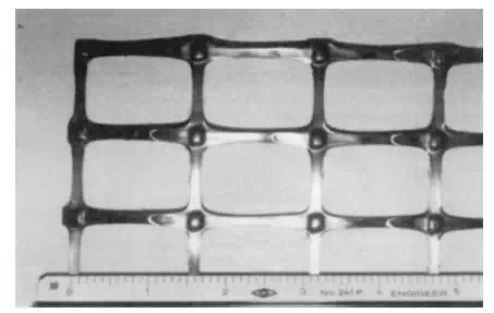
FIGURE 6.48 Photograph of a geogrid.
and redistribute stresses away from areas of high stress concentrations (such as beneath a wheel load).
Some of the limitations of geogrid are as follows:
1. Ultraviolet Light. Even geogrids produced of carbon black (i.e., ultraviolet stabilized geogrids) can degrade when exposed to long-term ultraviolet light. It is important to protect the geogrid from sunlight and cover the geogrid with fill as soon as possible.
2. Non-uniform Tensile Strength. Geogrids often have different tensile strengths in different directions as a result of the manufacturing process. For example, a Tensar SS-2 (BX1200) biaxial geogrid has an ultimate tensile strength of 2100 lb/ft in the main direction and only 1170 lb/ft in the minor (perpendicular) direction. It is essential that the engineer always check the manufacturer’s specifications and determine the tensile strengths in the main and minor directions.
3. Creep. Polymer material can be susceptible to creep. Thus, it is important to use an allowable tensile strength that does allow for creep of the geosynthetic. Oftentimes, this allowable tensile design strength is much less than the ultimate strength of the geogrid. For example, for a Tensar SS-2 (BX1200) biaxial geogrid, the manufacturer’s recommended tensile strength is about 300 lb/ft, which is only one-seventh the ultimate tensile strength (2100 lb/ft). The engineer should never apply an arbitrary factor of safety to the ultimate tensile strength, but rather obtain the allowable geogrid tensile design strength from the manufacturer.
Geotextiles
Geotextiles are the most widely used type of geosynthetic. Geotextiles are often referred to as fabric. For example, common construction terminology for geotextiles includes geofabric, filter fabric, construction fabric, synthetic fabric, and road-reinforcing fabric. As shown in Figs. 6.49 and 6.50, geotextiles are usually categorized as either woven or nonwoven, depending on the type of manufacturing process. Geotextiles are used for many different purposes, as follows:
1. Soil Reinforcement. Used for subgrade stabilization, slope reinforcement, and mechanically stabilized earth retaining walls. Also used to strengthen the junction between the top of soft clays and overlying embankments.
2. Sediment Control. Used as silt fences to trap sediment on-site.
3. Erosion Control. Installed along channels, under riprap, and used for shore and beach protection.
4. Asphalt Overlay. Used in asphalt overlays to reduce reflective cracking.
5. Separation. Used between two dissimilar materials, such as an open graded base and a clay subgrade, in order to prevent contamination.
6. Filtration and Drainage. Used in place of a graded filter where the flow of water occurs across (perpendicular to) the plane of the geotextile. For drainage applications, the water flows within the geotextile.
Probably the most common usage of geotextiles is for filtration (flow of water through the geotextile). For filtration, the geotextile should be at least 10 times more permeable than the soil. In addition, the geotextile must always be placed
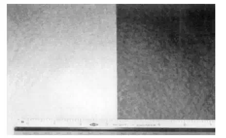
FIGURE 6.49 Photograph of nonwoven geotextiles. The geotextile on the left has no ultraviolet protection, while the geotextile on the right has ultraviolet protection.
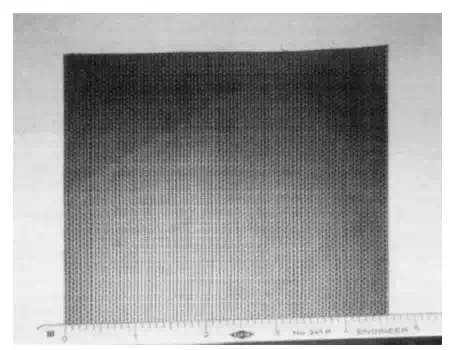
FIGURE 6.50 Photograph of a woven geotextile.
between a less permeable (i.e., the soil) and a more permeable (i.e., the open graded gravel) material. An inappropriate use of a geotextile would be to wrap it around a drainage pipe and then cover the geotextile with open-graded gravel. This is because the geotextile would then have more permeable material on both sides of the geotextile and it would tend to restrict flow.
Two important design properties for geotextiles used as filtration devices are that they have an adequate flow capacity and a proper soil retention capability:
1. Flow Capacity. Although specifications have been developed that limit the open area of the filtration geotextile to 10% or even 5%, it is best to have a larger open area to develop an adequate flow capacity.
2. Soil Retention Capability. The apparent opening size (AOS), also known as the equivalent opening size (EOS), determines the soil retention capability. The AOS is often expressed in terms of opening size (mm) or equivalent sieve size (e.g., AOS 40–70 indicates openings equivalent to the No. 40 to No. 70 sieves). Obviously, if the geotextile openings are larger than the largest soil particle diameter, then all of the soil particles will migrate through the geotextile and clog the drainage system. A common recommendation is that the required AOS be less than or equal to D85 (grain size corresponding to 85% percent passing).
Some of the limitations of geotextile are as follows:
1. Ultraviolet Light. Geotextile that has no ultraviolet light protection can rapidly deteriorate. For example, certain polypropylene geotextiles lost 100% of their strength after only 8 weeks of exposure.
2. Sealing of Geotextile. When the geotextile is used for filtration, an impermeable soil layer can develop adjacent the geotextile if it has too low an open area or too small an AOS.
3. Construction Problems. Some of the more common problems related to construction with geotextiles are as follows (G. N. Richardson and D. C. Wyant, ‘‘Geotextiles Construction Criteria’’):
(a) Fill placement or compaction techniques damage the geotextile.
(b) Installation loads are greater than design loads, leading to failure during construction.
(c) Construction environment leads to a significant reduction in assumed fabric properties, causing failure of the completed project.
(d) Field seaming or overlap of the geotextile fails to fully develop desired fabric mechanical properties.
(e) Instabilities during various construction phases may render a design inadequate even though the final product would have been stable.
Geomembranes
Common construction terminology for geomembranes includes liners, membranes, visqueen, plastic sheets, and impermeable sheets. Geomembranes are used almost exclusively as barriers to reduce water or vapor migration through soil (see Fig. 6.51). For example, a common usage for geomembranes is for the lining and capping systems in municipal landfills. For liners in municipal landfills, the thickness
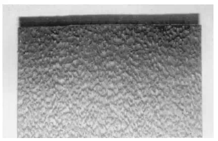
FIGURE 6.51 Photograph of a geomembrane, which has a surface texture for added friction
of the geomembrane is usually at least 80 mil. In the United States, one mil is one thousandth of an inch. Some of the limitations of geomembranes are as follows:
1. Puncture Resistance. The geomembrane must be thick enough so that it is not punctured during installation and subsequent usage.
2. Slide Resistance. Slope failures have developed in municipal liners because of the smooth and low frictional resistance between the geomembrane and overlying or underlying soil. Textured geomembranes (such as shown in Fig. 6.51) have been developed to increase the frictional resistance of the geomembrane surface.
3. Sealing of Seams. A common cause of leakage through geomembranes is due to inadequate sealing of seams. The following are different methods commonly used to seal geomembrane seams (M. P. Rollings and R. S. Rollings, ‘‘Geotechnical Materials in Construction,’’ McGraw-Hill Publishing Co., New York):
(a) Thermal Fusion. Suitable for thermoplastics. Adjacent surfaces are melted and then pressed together. Commercial equipment is available that uses a heated wedge (most common) or hot air to melt the materials. Also, ultrasonic energy can be used for melting rather than heat.
(b) Solvent-Based Systems. Suitable for materials that are compatible with the solvent. A solvent is used with pressure to join adjacent surfaces. Heating may be used to accelerate the curing. The solvent may contain some of the geomembrane polymer already dissolved in the solvent liquid (bodied solvent) or an adhesive to improve the seam quality.
(c) Contact Adhesive. Primarily suitable for thermosets. Solution is brushed onto surfaces to be joined, and pressure is applied to ensure good contact. Upon curing, the adhesive bonds the surfaces together.
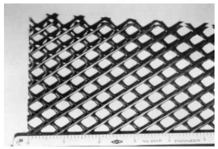
FIGURE 6.52 Photograph of a geonet.
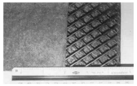
FIGURE 6.53 Photograph of a geocomposite. The geocomposite consists of a geonet having a textured geomembrane on top, and a filter fabric (geotextile) on the bottom.
(d) Extrusion Welding. Suitable for all polyethylene’s. A ribbon of molten polymer is extruded over the edge (fillet weld) or between the geomembrane sheets (flat weld). This melts the adjacent surfaces, which are then fused together upon cooling.
Geonets and Geocomposites
Geonets are three-dimensional netlike polymeric materials used for drainage (flow of water within the geosynthetic). Figure 6.52 shows a photograph of a geonet. Geonets are usually used in conjunction with a geotextile and/or geomembrane and hence are technically a geocomposite.
Depending on the particular project requirements, different types of geosynthetics can be combined together to form a geocomposite. For example, a geocomposite consisting of a geotextile and a geomembrane provides for a barrier that has increased tensile strength and resistance to punching and tearing. Figure 6.53 shows a photograph of a geocomposite consisting of a textured geomembrane, geonet, and geotextile (filter fabric).
Geosynthetic Clay Liners
Geosynthetic clay liners are frequently used as liners for municipal landfills. The geosynthetic clay liner typically consists of dry bentonite sandwiched between two geosynthetics. When moisture infiltrates the geosynthetic clay liner, the bentonite swells and creates a soil layer having a very low hydraulic conductivity, transforming it into an effective barrier to moisture migration.