For low-rise elevators, hydraulic equipment may be used to supply the lift. Two basic designs are available: one where the car sits atop a plunger or piston which operates in a pressure cylinder (Fig. 16.15), and the other where two plungers are located inside the elevator shaft to lift the elevator either by direct connection to the car frame or indirectly using hoist ropes. Oil serves as the pressure fluid and is supplied through a motor-driven positive-displacement pump, actuated by an electric-hydraulic control system.
To raise the car, the pump is started, discharging oil into the pressure cylinder and forcing the plunger up. When the car reaches the desired level, the pump is stopped. To lower the car, oil is released from the pressure cylinder and is returned to a storage tank.
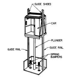
FIGURE 16.15 Hydraulic elevator.
Single-bearing cylinders (Fig. 16.16a) are a simple type that operate like a hydraulic jack. They are suitable for elevator and sidewalk lifts where the car is guided at top and bottom, preventing eccentric loading from exerting side thrust on the cylinder bearing. A cylinder of heavy steel usually is sunk in the ground as far as the load rises. The plunger, of thick-walled steel tubing polished to a mirror finish, is sealed at the top of the cylinder with compression packing. Oil is admitted under pressure near the top of the cylinder, while air is removed through a bleeder.
A different cylinder design should be used where the car or platform does not operate in guides. One type capable of taking off-balance loads employs a two-bearing plunger (Fig. 16.16b). The bearings are kept immersed in oil.
Another type, suitable for general industrial applications, has a movable bearing at the lower end of the plunger to give support against heavy eccentric loads (Fig. 16.16c). At the top of the cylinder, the plunger is supported by another bearing.
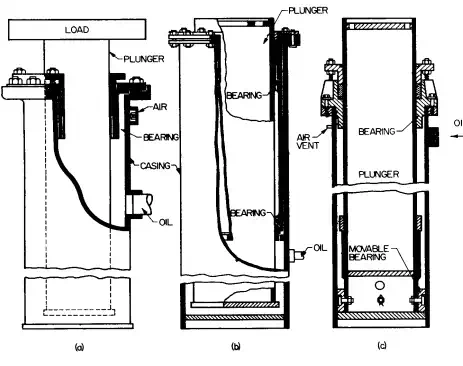
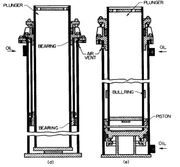
FIGURE 16.16 Jacks commonly used for hydraulic elevators: (a) single-bearing plunger for guided loads; (b) two-bearing plunger for off-balance loads; (c) movable-bearing plunger for heavy service; (d) cage bearing for long-stroke service; (e) double-acting plunger.
For long-stroke service, a cage-bearing type can be used (Fig. 16.16d). The cage bearing is supported by a secondary cylinder about 3 ft below the main cylinder head. Oil enters under pressure just below the main cylinder head, passes down through holes in the bearing, and lifts the plunger.
When the car or platform is not heavy enough to ensure gravity lowering, a double-acting cylinder may be used (Fig. 16.16e). To raise the plunger, oil is admitted under pressure below the piston; to lower it, oil is forced into the cylinder near the top, above the piston, and flows out below. Jack plunger sizes for the various types range from 21 ⁄2 in in diameter for small low-capacity lifts to 18 in for large lifts, operating at 150 to 400 psi.
Hydraulic elevators have several advantages over electric elevators: They are somewhat less expensive and simpler. The car and its frame rest on or beside the hydraulic plunger that raises and lowers them. There are sometimes wire ropes. No overhead equipment or penthouse is required. Without heavy overhead loads, hoist way columns and footings can be smaller. Car safeties or speed governors are only required on the roped type. Speed of the elevator is low; so the bumpers need be only heavy springs.
Capacity of hydraulic passenger elevators usually ranges from 1200 to 5000 lb at speeds from 75 to 150 ft/min. With gravity lowering, down speed may be 1.5 to 2 times up speed. So the average speed for a round trip can be considerably higher than the up speed. Standard hospital elevators have capacities of 3500 to 5000 lb at speeds of 75 to 150 ft/min.
Capacity of standard freight elevators ranges from 2500 to 8000 lb at 50 to 125 ft/min, but they can be designed for much greater loads.