A bearing capacity failure is defined as a foundation failure that occurs when the shear stresses in the soil exceed the shear strength of the soil. Bearing capacity failures of foundations can be grouped into three categories.
1. General Shear (Fig. 6.24). As shown in Fig. 6.24, a general shear failure involves total rupture of the underlying soil. There is a continuous shear failure of the soil (solid lines) from below the footing to the ground surface. When the load is plotted versus settlement of the footing, there is a distinct load at which the foundation fails (solid circle), and this is designated  . The value of divided by the width (B) and length (L) of the footing is considered to be the ‘‘ultimate bearing capacity’’ () of the footing. The ultimate bearing capacity has been defined as the bearing stress that causes a sudden catastrophic failure of the foundation. Note in Fig. 6.24 that a general shear failure ruptures and pushes up the soil on both sides of the footing. For actual failures it the field, the soil is often pushed up on only one side of the footing with subsequent tilting of the structure. A general shear failure occurs for soils that are in a dense or hard state.
2. Punching Shear (Fig. 6.25). As shown in Fig. 6.25, a punching shear failure does not develop the distinct shear surfaces associated with a general shear failure. For punching shear, the soil outside the loaded area remains relatively uninvolved and there is minimal movement of soil on both sides of the footing.

FIGURE 6.24 General shear foundation failure for soil in a dense or hard state.
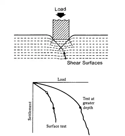
FIGURE 6.25 Punching shear foundation failure for soil in a loose or soft state
The process of deformation of the footing involves compression of soil directly below the footing as well as the vertical shearing of soil around the footing perimeter. As shown in Fig. 6.25, the load settlement curve does not have a dramatic break, and for punching shear, the bearing capacity is often defined as the first major nonlinearity in the load-settlement curve (open circle). A punching shear failure occurs for soils that are in a loose or soft state.
3. Local Shear Failure (Fig. 6.26). As shown in Fig. 6.26, local shear failure involves rupture of the soil only immediately below the footing. There is soil bulging on both sides of the footing, but the bulging is not as significant as in general shear. Local shear failure can be considered as a transitional phase between general shear and punching shear. Because of the transitional nature of local shear failure, the bearing capacity could be defined as the first major nonlinearity in the load-settlement curve (open circle) or at the point where the settlement rapidly increases (solid circle). A local shear failure occurs for soils that have a medium density or firm state.
The documented cases of bearing capacity failures indicate that usually the following three factors (separately or in combination) are the cause of the failure:

FIGURE 6.26 Local shear foundation failure, which is a transitional phase between general shear and punching shear failures
1. There was an overestimation of the shear strength of the underlying soil.
2. The actual structural load at the time of the bearing capacity failure was greater than that assumed during the design phase
3. The site was altered, such as the construction of an adjacent excavation, which resulted in a reduction in support and a bearing capacity failure.
A famous case of a bearing capacity failure is the Transcona grain elevator, located at Transcona, Manitoba, Canada, near Winnipeg. Figure 6.27 shows the October 1913 failure of the grain elevator. At the time of failure, the grain elevator was essentially fully loaded. The foundation had been constructed on clay that was described as a stiff clay. Note in Fig. 6.27 that the soil has been pushed up on only one side of the foundation, with subsequent tilting of the structure.
Bearing Capacity for Shallow Foundations
As indicated in Table 6.2, common types of shallow foundations include spread footings for isolated columns, combined footings for supporting the load from more than one structural unit, strip footings for walls, and mats or raft foundations constructed at or near ground surface. Shallow footings often have an embedment that is less than the footing width.
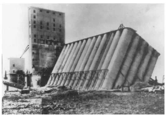
FIGURE 6.27 Transcona grain elevator bearing capacity failure.
Bearing Capacity Equation
The most commonly used bearing capacity equation is the equation developed by Terzaghi (‘‘Theoretical Soil Mechanics,’’ John Wiley & Sons, Inc., New York). For a uniform vertical loading of a strip footing, Terzaghi assumed a general shear failure (Fig. 6.24) in order to develop the following bearing capacity equation:
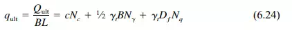
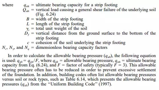
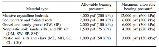
TABLE 6.14 Allowable Bearing Pressures
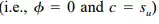
There are many charts, graphs, and figures that present bearing capacity factors developed by different engineers and researchers based on varying assumptions. For example, Fig. 6.28 presents bearing capacity factors Nc, N
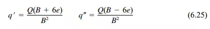
, and Nq , which automatically incorporate allowance for punching and local shear failure. Another example is Fig. 6.29, which presents bearing capacity factors that have not been adjusted for punching or local shear failure. Figure 6.29 also presents the bearing capacity equations for square, rectangular, and circular footings. The equations for granular soil (i.e., cohesionless soil, c 0) and for a total stress analysis for cohesive soil
are also shown in Fig. 6.29.
Other Footing Loads
In addition to the vertical load acting on the footing, it may also be subjected to a lateral load. A common procedure is to treat lateral loads separately and resist the lateral loads by using the soil pressure acting on the sides of the footing (passive pressure) and the frictional resistance along the bottom of the footing.
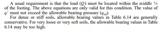
It is always desirable to design and construct shallow footings so that the vertical load is applied at the center of gravity of the footing. For combined footings that carry more than one vertical load, the combined footing should be designed and constructed so that the vertical loads are symmetric. There may be design situations where the footing is subjected to a moment, such as where there is a fixed-end connection between the building frame and the footing. This moment can be represented by a load Q that is offset a certain distance (known as the eccentricity) from the center of gravity of the footing. For other projects, there may be property line constraints and the load must be offset a certain distance (eccentricity) from the center of gravity of the footing. Because an eccentrically loaded footing will create a higher bearing pressure under one side as compared to the opposite side, one approach is to evaluate the actual pressure distribution beneath the footing. The usual procedure is to assume a rigid footing (hence linear pressure distribution) and use the section modulus (1 ⁄6B2 ) in order to calculate the largest and lowest bearing pressure. For a footing having a width B, the largest (q) and lowest (q) bearing pressures are as follows:
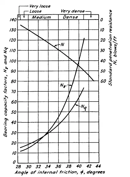
FIGURE 6.28 Bearing capacity factors N
and Nq, which automatically incorporate allowance for punching and local shear failure.
where  = largest bearing pressure underneath the footing, which is located along the same side of the footing as the eccentricity
 = lowest bearing pressure underneath the footing, which is located at the opposite side of the footing
Q = load applied to the footing (kN per linear m of footing length or lb per linear ft of footing length)
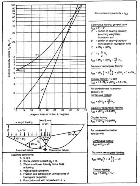
FIGURE 6.29 Bearing capacity factors Ny, Nq, and Nc, which do not include allowance for punching or local shear failure.
e = eccentricity of the load Q; i.e., the lateral distance from Q to the center of gravity of the footing
B = width of the footing
Bearing Capacity for Deep Foundations in Granular Soil
Deep foundations are used when the upper soil stratum is too soft, weak, or compressible to support the foundation loads. Deep foundations are also used when there is a possibility of the undermining of the foundation. For example, bridge piers are often founded on deep foundations to prevent a loss of support due to flood conditions which could cause river bottom scour. The most common types of deep foundations are piles and piers that support individual footings or mat foundations (Table 6.2). Piles are defined as relatively long, slender, column-like members often made of steel, concrete, or wood that are either driven into place or castin-place in predrilled holes. Common types of piles are as follows:
Batter Pile
A pile driven in at an angle inclined to the vertical to provide high resistance to lateral loads.
End-Bearing Pile
A pile whose support capacity is derived principally from the resistance of the foundation material on which the pile tip rests. End-bearing piles are often used when a soft upper layer is underlain by a dense or hard stratum. If the upper soft layer should settle, the pile could be subjected to down drag forces, and the pile must be designed to resist these soil-induced forces.
Friction Pile
A pile whose support capacity is derived principally from the resistance of the soil friction and/or adhesion mobilized along the side of the pile. Friction piles are often used in soft clays where the end-bearing resistance is small because of punching shear at the pile tip.
Combined End-Bearing and Friction Pile
A pile that derives its support capacity from combined end-bearing resistance developed at the pile tip and frictional and/or adhesion resistance on the pile perimeter.
A pier is defined as a deep foundation system, similar to a cast-in-place pile, that consists of a column-like reinforced concrete member. Piers are often of large enough diameter to enable down-hole inspection. Piers are also commonly referred to as drilled shafts, bored piles, or drilled caissons.
Many other methods are available for forming deep foundation elements. Examples include earth stabilization columns, such as (NAVFAC DM-7.2, 1982):
Mixed-in-Place Piles
A mixed-in-place soil-cement or soil-lime pile.
Vibro-Replacement Stone Columns
Vibroflotation or other method is used to make a cylindrical, vertical hole that is filled with compacted gravel or crushed rock.
Grouted Stone Columns
Similar to the above but includes filling voids with bentonite-cement or water-sand-bentonite cement mixtures.
Concrete Vibro Columns
Similar to stone columns, but concrete is used instead of gravel.
Several different items are used in the design and construction of piles, including:
Engineering Analysis
Based on the results of subsurface exploration and laboratory testing, the bearing capacity of the deep foundation can be calculated in a similar manner to the previous section on shallow foundations. This section will describe the engineering analyses for deep foundations in granular and cohesive soil.
Field Load Tests
Prior to the construction of the foundation, a pile or pier could be load tested in the field to determine its carrying capacity. Because of the uncertainties in the design of piles based on engineering analyses, pile load tests are common. The pile load test can often result in a more economical foundation than one based solely on engineering analyses.
Application of Pile Driving Resistance
Often the pile driving resistance (i.e., blows per ft) is recorded as the pile is driven into place. When the anticipated bearing layer is encountered, the driving resistance (blows per ft) should substantially increase.
Specifications and Experience
Other factors that should be considered in the deep foundation design include governing building code or agency requirements and local experience.
End Bearing Pile for Granular Soil
For an end bearing pile or pier, the bearing capacity equation can be used to determine the ultimate bearing capacity  . When we compare the second and third term in Eq. (6.24), the value of B (width of pile) is much less than the embedment depth (Dƒ ) of the pile. Therefore, the second term in Eq. (6.24) can be neglected. Assuming granular soil (c = 0), Eq. (6.24) reduces to the following:
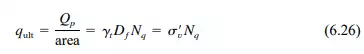
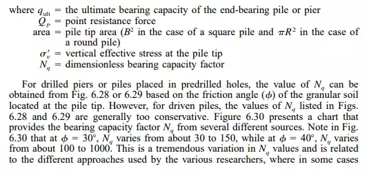
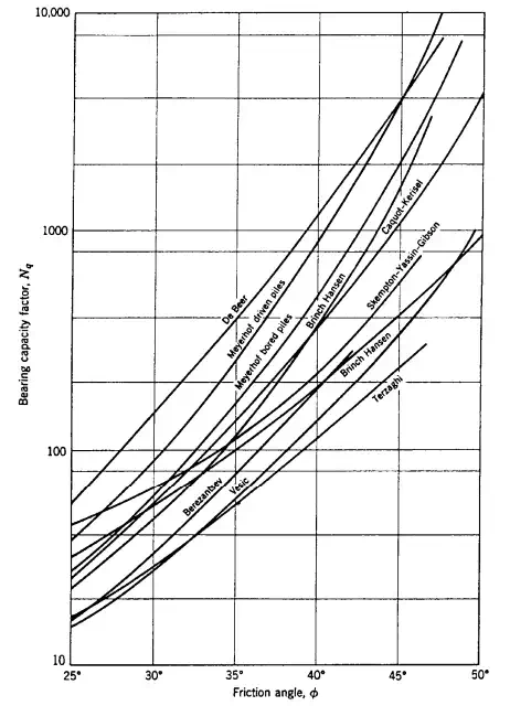
FIGURE 6.30 Bearing capacity factor Nq as recommended by various researchers for deep foundations.
the basis of the relationship shown in Fig. 6.30 is theoretical and in other cases the relationship is based on analysis of field data such as pile load tests. There is a general belief that the bearing capacity factor Nq is higher for driven piles than for shallow foundations. One reason for a higher Nq value is the effect of driving the pile, which displaces and densifies the cohesionless soil at the bottom of the pile. The densification could be due to both the physical process of displacing the soil and the driving vibrations. These actions would tend to increase the friction angle of the granular soil in the vicinity of the driven pile. Large-diameter piles would tend to displace and densify more soil than smaller-diameter piles.
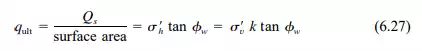
Friction Pile for Granular Soil
As the name implies, a friction pile develops its load carrying capacity due to the frictional resistance between the granular soil and the pile perimeter. Piles subjected to vertical uplift forces would be designed as friction piles because there would be no end-bearing resistance as the pile is pulled from the ground.
Based on a linear increase in frictional resistance with confining pressure, the average ultimate frictional capacity  can be calculated as follows:
Combined End-Bearing and Friction Pile in Granular Soil
Piles and piers subjected to vertical compressive loads and embedded in a deposit of granular soil are usually treated in the design analysis as combined end-bearing and friction piles or piers. This is because the pile or pier can develop substantial load-carrying capacity from both end-bearing and frictional resistance. To calculate the ultimate pile or pier capacity for a condition of combined end-bearing and friction, the value of Qp from Eq. (6.26) is added to the value of Qs from Eq. (6.27). Usually the ultimate capacity is divided by a factor of safety of 3 in order to calculate the allowable pile or pier load.
Pile Groups in Granular Soil
The previous discussion dealt with the load capacity of a single pile in cohesionless soil. Usually pile groups are used to support the foundation elements, such as a group of piles supporting a pile cap or a mat slab. In loose sand and gravel deposits, the load-carrying capacity of each pile in the group may be greater than that of a single pile because of the densification effect due to driving the piles. Because of this densification effect, the load capacity of the group is often taken as the load capacity of a single pile times the number of piles in the group. An exception would be a situation where a weak layer underlies the cohesionless soil. In this case, group action of the piles could cause them to punch through the granular soil and into the weaker layer or cause excessive settlement of the weak layer located below the pile tips.
In order to determine the settlement of the strata underlying the pile group, the 2:1 approximation can be used to determine the increase in vertical stress ( for those soil layers located below the pile tip. If the piles in the group are principally end-bearing, then the 2:1 approximation starts at the tip of the piles (L bottom length of the pile group, B width of the pile group, and z depth below the tip of the piles, see Eq. 6.16). If the pile group develops its load-carrying capacity principally through side friction, then the 2:1 approximation starts at a depth of 2 ⁄3D, where D depth of the pile group.
Bearing Capacity for Deep Foundations in Cohesive Soil
The load-carrying capacity of piles and piers in cohesive soil is more complex than the analysis for granular soil. Some of the factors that may need to be considered in the analysis are as follows (AASHTO, ‘‘Standard Specifications for Bridges,’’ 16th ed., American Association of State Highway and Transportation Officials, Washington, DC):
· A lower load-carrying capacity of a pile in a pile group as compared to that of a single pile.
· The settlement of the underlying cohesive soil due to the load of the pile group.
· The effects of driving piles on adjacent structures or slopes. The ground will often heave around piles driven into soft and saturated cohesive soil.
· The increase in load on the pile due to negative skin friction (i.e., down-drag loads) from consolidating soil.
· The effects of uplift loads from expansive and swelling clays.
· The reduction in shear strength of the cohesive soil due to construction techniques, such as the disturbance of sensitive clays or development of excess pore water pressures during the driving of the pile. There is often an increase in load carrying capacity of a pile after it has been driven into a soft and saturated clay deposit. This increase with time is known as freeze or setup and is caused primarily by the dissipation of excess pore water pressures.
· The influence of fluctuations in the elevation of the groundwater table on the load-carrying capacity when analysed in terms of effective stresses.
Total Stress Analysis
The ultimate load capacity of a single pile or pier in cohesive soil is often determined by performing a total stress analysis. This is because the critical load on the pile, such as from wind or earthquake loads, is a short-term loading condition and thus the undrained shear strength of the cohesive soil will govern. The total stress analysis for a single pile or pier in cohesive soil typically is based on the undrained shear strength (Su =c) of the cohesive soil.
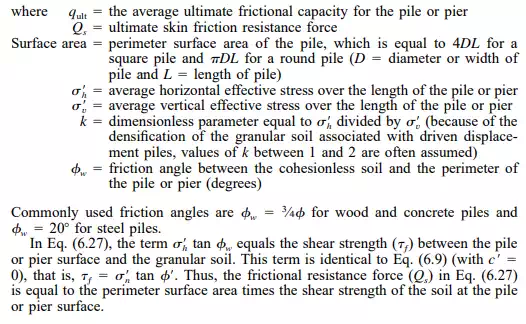
The ultimate load capacity of the pile or pier in cohesive soil would equal the sum of the ultimate end-bearing and ultimate side adhesion components. Using the Terzaghi bearing capacity equation (Eq. 6.24), the ultimate load capacity  of a single pile or pier in cohesive soil equals:
Pile Groups
The bearing capacity of pile groups in cohesive soils is normally less than the sum of individual piles in the group, and this reduction in group
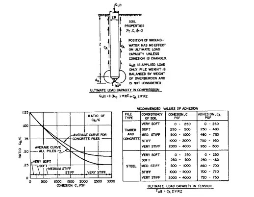
FIGURE 6.31 Ultimate capacity for a single pile or pier in cohesive soil.
capacity must be considered in the analysis. The ‘‘group efficiency’’ is defined as the ratio of the ultimate load capacity of each pile in the group to the ultimate load capacity of a single isolated pile. If the spacing between piles in the group is at a distance that is greater than about 7 times the pile diameter, then the group efficiency is equal to 1 (i.e., no reduction in pile capacity for group action). The group efficiency decreases as the piles become closer together in the pile group. Figure 6.32 can be used to determine the ultimate load capacity of a pile group in cohesive soil.
Similar to pile groups in cohesionless soil, the settlement of the strata underlying the pile group can be evaluated by using the 2:1 approximation to calculate the increase in vertical stress ( for those soil layers located below the pile tip. If the piles in the group develop their load-carrying capacity principally by end-bearing in cohesive soil, then the 2:1 approximation starts at the tip of the piles (L bottom length of the pile group, B width of the pile group, and z depth below the tip of the piles, see Eq. 6.16). If the pile group develops its load carrying capacity principally through cohesive soil adhesion along the pile perimeter, then the 2:1 approximation starts at a depth of 2 ⁄3 D, where D depth of the pile group.
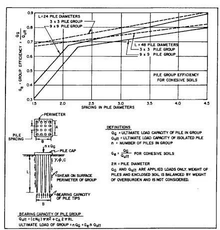
FIGURE 6.32 Ultimate capacity of a pile group in cohesive soil.


Comments are closed.