When water has little or no movement, suspended solids sink to the bottom under the force of gravity and form a sediment. You will recall that we discussed a similar process in estuaries, with solids separating from the water. This process is called sedimentation. In water treatment it is used to remove solids from waters which are high in sediment content, and also to remove particles rendered settleable by coagulation and flocculation.
The theory of sedimentation would seem to be quite simple. Earlier we had a widening river flowing more slowly, so if we make the settling tank large enough and the flow slow enough, this will enhance the rate of fall of the sediment towards the bottom of the tank.
What other factors do you think need to be known?
It will be necessary to know the density and the size of the particles to calculate their rate of fall. There should be no turbulence in the tank as it will tend to reduce settlement, and there must be an even flow through the tank to prevent a narrow stream flowing through quickly from one end to the other (i.e. channelling).
Because of these factors we shall now look at settlement in greater detail. Sedimentation tanks can be of various types: rectangular with horizontal flow, circular with radial flow, or hopper-bottomed with upward flow (Figure 23).
The circular and rectangular tanks are equipped with mechanical sludge-scraping devices to remove the wet sludge that has settled. In hopper-bottomed tanks, the sludge concentrates at the bottom of the hopper from where it can be drawn off. In radial and horizontal flow tanks any floating material is skimmed from the surface by a blade carried by the scraping mechanism, and is discharged to be combined with the settled sludge. In upward flow tanks, the main sludge removal is from the top of the sludge blanket (see Figure 23(c)).
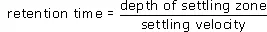
Figure 23 Typical sedimentation tanks: (a) rectangular horizontal flow tank; (b) circular, radial-flow tank; (c) hopper-bottomed, upward flow tank
An idealised representation of a circular radial-flow tank is shown in Figure 24. There are four important zones in the tank:
(a) Inlet zone – at the central well, which has a round baffle plate, the flow is established in a uniform radial direction so that short-circuiting does not take place.
(b) Settling zone – where settling is assumed to occur as the water flows towards the outlet.
(c) Outlet zone – in which the flow converges up and over the decanting weirs.
(d) Sludge zone – where settled material collects and is pumped out.

Figure 24 Radial-flow sedimentation tank
The performance of a settling tank is related to the settling velocity of the fine particles in suspension. The settling velocity is the speed at which the particles move downwards under gravity through the suspension, and for discrete particles this is dependent on the particle density and size. The retention time required by the particles to settle to the bottom of a settling tank is related to the settling velocity by the simple relationship
The time available for particles to settle out in the settling tank also depends on the flow rate of the suspension through the tank
This expression assumes that no short-circuiting takes place in the tank, i.e. that the water doesn’t flow straight from inlet to outlet.
Table 4 shows settling velocities for various types of suspended solids and the required retention times for sedimentation in a 3 m deep tank.
Table 4 Settling velocities for different types of suspended solids and the retention time required in a 3 m deep tank for sedimentation to occur
| Nature of solids | Settling velocity (mm s−1) | Retention time for settling to occur in 3 m deep tank (hours) |
| Clay, silt | 0.07 | 11.9 |
| Primary organic waste | 0.42 | 1.98 |
| Aluminium and iron flocs | 0.83 | 1.00 |
| Activated sludge | 2.00 | 0.42 |
| Grit | 20.00 | 0.042 |
Notice that to achieve a separation of materials with low settling velocities, the retention time in the settling tank must be increased. In practice, this can be achieved by increasing the settling tank volume or decreasing the flow rate of suspension through the tank.
Activity
100 m3 d−1 of a suspension of silt is passed through a settling tank with a 3 m deep settling zone. What is the effective settling zone area?
Reveal discussion
Self-assessment question
A circular radial-flow tank has a settling zone depth of 4 m and a settling zone area of 700 m2. What is the retention time necessary to remove organic detritus with settling velocities of 0.4 mm s−1 and greater? What flow rate is required through the tank?
In order to achieve the required retention time in the above SAQ, throughput of suspension must not be greater than 0.28 m3 s−1. But what if the same suspension was passed through a 2 m deep tank – half the depth? One might expect that in a shallow tank the same particles would reach the sludge zone at the bottom more quickly. Would this allow a larger throughput? Halving the tank depth would halve the retention time of particles in the tank; but would also halve the tank volume. So the flow rate through the shallower tank would be the same as for the deep tank. This independence of settling behaviour with depth has led to the development of shallow depth sedimentation tanks in which the flow is passed in parallel through a number of closely spaced inclined channels arranged in a device called a parallel plate separator (Figure 25). The slope of the settling channels is steep so that the tank is continuously self-cleaning (the solids slide off and go to the bottom of the tank). The advantage of such an arrangement is clear. For the same tank area, with n channels, throughput can be n-fold whilst retaining the same settling velocity in each channel.

Figure 25 A parallel plate separator within a sedimentation tank
The discussion so far has dealt with ‘ideal’ conditions in which particles settle under gravity without hindrance from other particles in the vicinity. An example of such a situation would be the settling of heavy grit particles or sand. There are, however, types of particles called flocculent particles which interact with other particles in their vicinity. An example would be organic suspended solids or the floc particles produced by chemical coagulation and flocculation of water, with a broad spectrum of sizes and surface characteristics.
Different-sized particles settle at different rates so that larger particles will overtake or collide with smaller particles. These collisions may result in coalescence into larger aggregates with an increasing settling velocity so that the typical path of a flocculent particle is curved (Figure 26), indicating the increasing velocity with depth. One important requirement of settling tanks for treating flocculent suspensions is, therefore, that the depth should be great enough to provide the opportunity for particle agglomeration to occur. This is in contrast to the behaviour of discrete particles whose settling behaviour is independent of depth. The effect of tank depth on removal efficiency is shown in Figure 26. If the tank depth is reduced by half, the retention time is halved and the depth reached by each type of particle during that time is reduced. Nevertheless the discrete particle will again just reach the bottom of the reduced depth tank, whereas the flocculent particle will not have reached the tank floor and will be drawn off in the tank outflow. This is a simplification of what actually happens inside a sedimentation tank; however, it is generally considered that the overall effect of reducing settling tank depth is to reduce removal efficiency when treating flocculent particles.
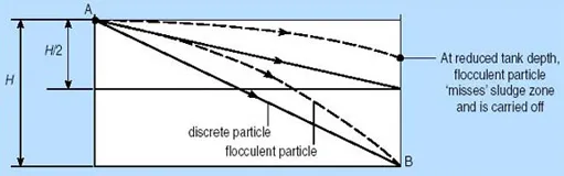
Figure 26 Effect of tank depth on removal of discrete and flocculent particles
Settlement tanks must therefore be designed deep enough to allow all particles to settle, and also to have flow such that settled solids are not disturbed and carried over the weir at the outlet of the settlement tank.
A parameter known as the surface overflow rate or surface loading rate is used in the design of sedimentation tanks.
This is defined as
Typical values for the surface loading rate range from 30 to 45 m3 m−2 d−1.