The objective of bending test on a wooden beam is to study the bending or flexural behavior of the wooden beam and to determine the Modulus of Elasticity and Modulus of Rupture of the wood.
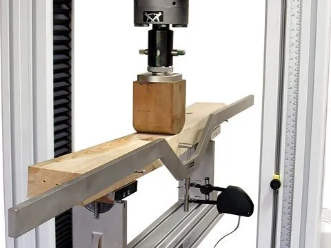
Fig 1: Wooden Beam Test.
Equipment Required
- 10 ton Buckton UTM
- Deflection Gauges
- Wooden Beam
- Measuring Tape
Theory and Principle
The modulus of elasticity in bending and bending strength is determined by applying a load to the center of a test piece supported at two points. The modulus of elasticity is calculated by using the slope of the linear region of the load-deflection curve.
The bending strength of each test piece is calculated by determining the ratio of the bending moment M, at the maximum load Fmax, to the moment of its full cross-section.
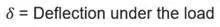
For a simply supported beam with central loading, deflection under the load is given by :
Where,
W =Applied load
L = Effective span of the beam
E = Young’s Modulus of wood
I = Moment of inertia
Test Procedure
- Insert the bending device in the UTM.
- Measure the width and depth of the wooden beam.
- Adjust the support for the required distance and clamp to the lower table.
- Fix the transverse test pan at the lower side of the lower cross head.
- Fix it on the rollers of the transverse test brackets such that the load comes at the center and measure the length of the span of the beam between the supports for central loading.
- Adjust the load pointer to zero by lifting the lower table. While applying the load, the deflection corresponding to each load is found out from the vernier scale on the UTM.
- Note down the maximum deflection and the maximum load.
Fig 2: Wooden beam while loading and after failure.
Observation and Calculation
b=____ mm, h= ____mm, l=____mm
Breaking Load (Pmax): _____ tons
Modulus of Rupture =
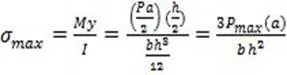
Modulus of Rupture is denoted in MPa
Modulus of Elasticity =
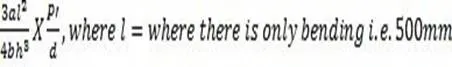
Modulus of Elasticity is denoted by GPa
Test Precautions
- Apply the loads gradually so that we can read the deflection against each reading easily.
- Remove the gauges before the failure load, otherwise, they may get damaged.
- Stay away from the machine when the load is being applied as the particles may cause an injury.

Comments are closed.