Scale drawings are used to illustrate items that it is not useful or convenient to draw at their actual size
This may be because drawing the item at full size would be unmanageable, or would not easily fit on a single sheet of paper (such as a building), or alternatively because items need to be drawn larger than full size to adequately represent all the detail that needs to be communicated (such as a complex connection).
The scale of drawings is described as a ratio using the notation:
| A distance at full size : The distance at the scale used that would be the same length. |
For example:
§ A full size drawing would be 1:1 (or sometimes 1/1 or ‘one to one’).
§ A half size drawing would be 1:2.
§ A tenth size drawing would be 1:10.
§ A double size drawing would be 2:1.
In the construction industry a range of scales are generally used depending on the nature of the drawing. For example:
§ A location plan at 1:1000.
§ A site plan at 1:200.
§ A floor plan at 1:100.
§ A room plan at 1:50.
§ A component drawing at 1:5.
§ An assembly drawing at 1:2.
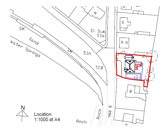
It is important that the scale used is noted on the drawing. In addition, because of the ease of reproducing, printing and re-sizing drawings, it is important to note the original sheet size that the scale was drawn at, so for example A4, A3, A2, A1, A0, and so on.
In some cases, it may be appropriate to use more than one scale on a single drawing, for example, to show the elevation of land across across a significant distance. In this case, differences in elevation might be illustrated at a larger scale and a smaller scale used for horizontal distances. Here, the scale might be noted on the axes of the drawing, or actual distances shown on the axes.
In other cases a scale might use more than one unit of measurement. For example, the length of an arrow on an air flow diagram might represent the velocity of the air, e.g. 1 cm = 0.1 m/s.
The use of computer aided drawing (CAD) and building information modelling (BIM) has introduced a new concept to this process, as in this case, digital models are created at full size. Drawings of any scale can then be generated from the model.