A ‘section drawing’, ‘section’ or ‘sectional drawing’ shows a view of a structure as though it had been sliced in half or cut along another imaginary plane.
For buildings, this can be useful as it gives a view through the spaces and surrounding structures (typically across a vertical plane) that can reveal the relationships between the different parts of the buildings that might not be apparent on plan drawings. Plan drawings are in fact a type of section, but they cut through the building on a horizontal rather than vertical plane.
The direction of the plane through which the section is cut is often represented on plan drawings and elevations by a line of long and short dashes, called a section plane. If there are a number of sections, the line may have letters at each end indicating the name of the section drawing and an arrow showing the direction that the view takes.
The section line can take an indirect route through a building if this helps show the most important features or junctions in the building, as illustrated on the drawing below.
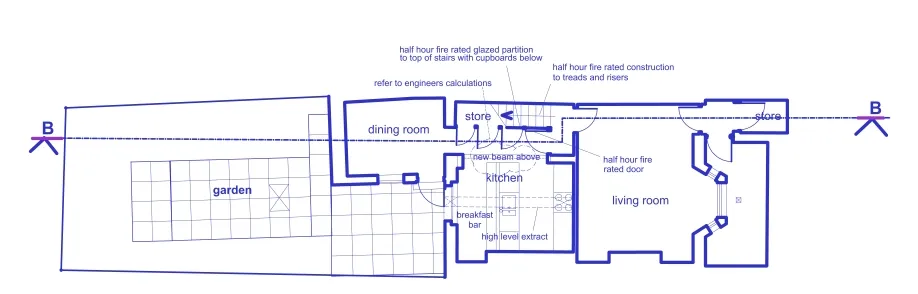
In this case, the section drawing would be named ‘Section B-B’.
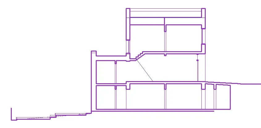
Shading, cross hatching or other fill styles and / or thicker lines can be used to indicate parts of the structure that have been cut through, such as walls, roofs and floors.
The scale of a section drawing will depend on the size of the building being drawn and the level of detail that needs to be shown. Sections may show the entire building, or may focus on a particular component, junction or assembly. In this case they can be similar to assembly drawings but differ in that they don’t usually include details of the actually assembly process.
Different types of cross hatching can be used to differentiate between different types of component on detailed sectional drawings. Standards exist for hatching that should be used on some common materials, for example, double diagonal lines indicate brickwork, a wave indicates insulation and so on.
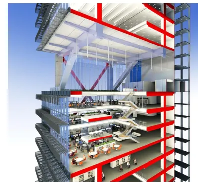
Perspective sections include 3D projection of the spaces beyond the section plane and can be used to give a graphical illustration of the relationship between spaces and building components as well as their depths that can be very helpful in trying to interpret a complex design.
Increasingly, section drawings can be generated automatically by 3D modelling software, including perspective sections where required.