A measured survey is a crucial part of any design development and should be undertaken prior to any design development. The end result of a measured survey is the production of computer-aided design (CAD) drawings which your architect/designer uses as a base for their new design. When sending a measured survey specification to your survey team, your architect will ask for a number of different drawing types depending on the size and complexity of the proposed design. This article aims to outline the various types of drawings they may specify.
Drawing Types Explained
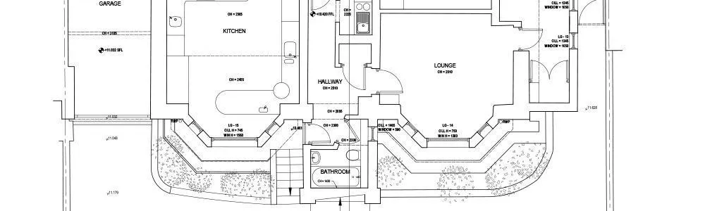
Floor Plan Drawings
Floor plan drawings are one of the most common drawing types in architecture and building engineering projects. A floor plan is a scaled drawing showing a view from above which clearly defines the relationship of rooms and areas to each other. Floor plans are important as they show elements of a building and where they are positioned. Elements include doors, windows, walls, stairs, overhead beams etc.
A floor plan is one of the first places a designer will start when coming up with their designs. They can help to understand the layout of a room and see whether furniture fits, and obtain accurate floor areas for contractor pricing.
Section Drawings
A section drawing shows a cut through a building as if it has been sliced with a knife and one part has been removed. A section through a building is very useful for a designer as they can clearly see the relationships of the spaces to each other, which may not be clear on a plan. They are also useful for getting a clearer picture of heights within a building and can show important relationships between items such as ceiling and floor levels. The direction and location of the section lines are usually stated on the floor plan drawing and if drawn correctly will show the section as it is at that exact location.
Elevation Drawing
An elevation drawing is a view showing one side of a building. It’s the most common method to show the outside of a building and is useful as it can clearly show what an existing or proposed situation looks like. An elevation drawing can pick up basic information such as the location of doors, windows and steps, as well as more complex features of the building’s facade, such as architectural details above windows and ironmongery.
Depending on the building works taking place an elevation will be required on the building faces that are being changed. For example, a rear extension may require both a rear elevation and a side elevation drawing.
Interested in our measured surveys?
Roof Plan
A roof plan is a view looking from overhead, and it details the arrangement of the roof layout. It will outline the arrangement of the roof as well as noting where items such as the ridges, chimneys, eaves extents are. Roof plans are useful for designers as the layout of a roof could impact a new construction such a loft conversion. Having a good idea of the roof’s specifications can help save money and avoid future problems as issues can be sorted prior to construction.
Surveying a roof can be difficult due to access issues and not being able to see it from ground level. If this is the case then sometimes a roof plan will need to be assumed using internal measurements within the loft area.
Site Plan
A site plan can be defined as a slightly simplified topographical survey. This will show your building in relation to important features such as property boundaries, other buildings on site, large trees etc. A site plan may also show where inspection chambers are and note their details, including invert levels and drain run directions. Sometimes it is crucial to know where your proposed development sits in regards to other features so issues like planning permission are nullified.