| Isometric drawing is way of presenting designs/drawings in three dimensions. In order for a design to appear three dimensional, a 30 degree angle is applied to its sides. The cube opposite, has been drawn in isometric projection. | 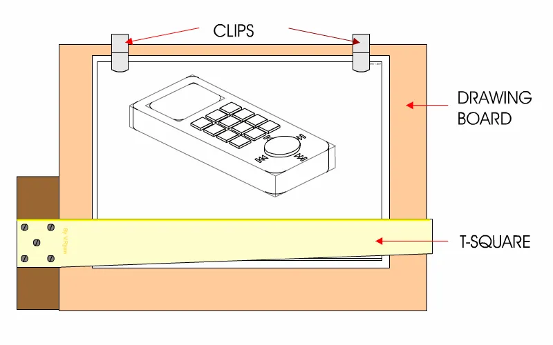 |
| FREE HAND SKETCHING IN ISOMETRIC: Designs drawn in isometric projection are normally drawn precisely using drawing equipment. However, designers find ‘free hand’ sketching in isometric projection useful. The mobile phone / music player opposite, has been sketched in free hand isometric projection. It allows the designer to draw in 3D quickly and with a reasonable degree of accuracy. The design is still drawn at a 30 degree angle, although this is estimated, rather than drawn with graphics equipment. Limited colour/shade has been added to the menu of the phone. This means that the sketch is not presented entirely as a ‘plain’ design. These drawings are quick sketches, that allow the designer to put his / her thoughts down on paper rapidly. This helps him/her develop an idea or design concept quickly, without the need for complex drawings, at an early stage in the design process. In early meetings with a client, the designer can display 3D drawings of this type in order to ascertain if the design is developing the way the client wants. | 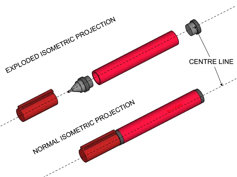 |
| Drawing in isometric projection, normally means drawing very accurately using traditional drawing equipment. This includes using T-Square, set squares and measuring accurately. The isometric drawing seen opposite has been drawn precisely, using skills learned through hours of practice. When these skills have been developed, sketching in isometric becomes second nature. EXPLODED ISOMETERIC PROJECTION Designers use ‘exploded’ views, often drawn in isometric projection, to show parts of products that are hidden from sight. For example, all the parts of the pen, drawn below, can be seen because it has been taken apart using the drawing technique called ‘Exploded Isometric Projection’.With exploded isometric projection, all the parts are in line with each other, along a centre line. This is drawn precisely through the centre of the product being drawn. With a normal isometric drawing, all the parts are in their assembled positions. This means that vital hidden detail cannot be seen. Designers also use exploded views to explain their designs to clients/customers and manufacturers. Furthermore, exploded views of products are often supplied to customers, who in turn assemble the product. A good example of this is ‘knock down’ furniture. When the flat pack is opened, an instruction sheet or booklet explains how the furniture is assembled, often in the form of isometric exploded views. The drawings seen below, were supplied with an instruction booklet. They are two of numerous diagrams drawn in isometric projection. They help explain how the cabinet and all its component parts are assembled, to form the finished product.These are accurate drawings constructed by a designer, that explain how the product he/she has designed is assembled. 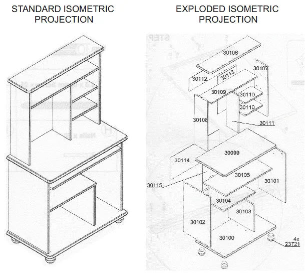 | |
My WordPress Blog