Introduction —first attempt
In the Western world, we are accustomed to the linear perspective, which tries to achieve visual realism in paintings of 3-dimensional environments. The linear perspective, which was perfected throughout the 17th century in Europe, is based on Euclidean optics: the eye as a point object that catches straight light rays and that senses only the colour, the intensity and the angle of the rays, not their length.
Another perspective had developed in oriental art: the “Chinese perspective” was an intrinsic part of the classical scroll painting (actually, “Chinese perspective” is a bit of a misnomer because the same perspective was also used in Japanese art and that of other oriental countries). A typical Chinese scroll painting had a size of approximately 40 centimetres high by several meters wide. One views the painting by unrolling it (from right to left) on a table in segments of about 60 centimetres wide. The Chinese scroll paintings show a development in time —a form of “narrative art”, in contrast to the paintings that were made in Europe at the time, which show a “situation” rather than a development.
For these scroll paintings, the Chinese painters needed a perspective that had no explicit vanishing points; every scene of the scroll painting would be seen individually and a vanishing point that lies outside the viewport creates a disoriented view of the scene. (For the same reason, the Chinese scroll paintings usually do not have an explicit light source or cast shadows.) The Chinese painters solved the problem by drawing the lines along the z-axis as parallel lines in the scroll painting. This has the effect of placing the horizon at an imaginary line, infinitely high above the painting. The axonometric projection is a technical term for a class of perspectives to which the Chinese parallel perspective also belongs. These perspectives are not only lacking a vanishing point, they also have a few other, mostly useful, characteristics. These are discussed below.
A scroll painting
Introduction —second attempt
Technical drawings need to be precise, accurate and unambiguous. Technical drawings are for engineers and fitters. National institutes formally standardize technical drawings, so that a carpenter will build the particular chair that the furniture designer imagined. Technical drawings are a means of communication, for those who can understand it.
If the world were populated by engineers, nothing else would matter —but it isn’t and engineers (and fitters and carpenters alike) need to communicate with managers and customers. The problem is, of course, that technical drawings are difficult to decipher for the uninitiated. Although they show an object from up to six angles, all of those angles are unrealistic: directly from the front, directly from above, etc. What is needed to convey the general shape of the object is a perspective drawing that shows three sides of a cube at once.
At this point, the next issue is: how? Engineers being as they are, they want a simple technique that does not loose much of the accuracy of the original drawings and that does not require artistic skills. Also note that in most cases the object that you must draw does not yet exist, so usually you cannot take a look at the object to get a sense for its proportions. That makes it nearly undoable to adequately position the vanishing points and to estimate the foreshortening.
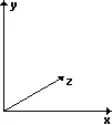
The compromise, that became to be known as axonometry, is a drawing technique where the orthogonal x-, y- and z-axes of the (3-dimensional) world space are projected to (non-orthogonal) axes on paper. In the projection, the y-axis usually remains the vertical axis, the z-axis is skewed and the x-axis may either be horizontal, as in the figure at the right, or be skewed as well. A more important property of axonometry is its fixed relation between sizes of objects in world space and those on projected space, independent of the positions of the objects in projected space. In linear perspective, objects become smaller when they move farther away; not so in axonometric perspective. This means that you can measure the size of an object of a axonometric drawing and know how big the real object is (you need to know the scale of the drawing and the properties of the projection, but nothing else), something that cannot be done with linear perspective. This leads to the name of the projection: the word “axonometry” means “measurable from the axes”.
Although there are countless possible axonometric projections, only two are standardized for technical drawings. These are described in detail below.
Introduction —third attempt
Computer games have traditionally been brimming with graphics and animation. In fact, games are categorized according to the kind of graphics they used. Two popular types of games are “platform games” where you look from the side, and “board games” where you look mostly from above. These games also have in common that they often use tiles to build the “world” from. Given these similarities, and given the dullness of the unrealistic viewpoints of both platform games and board games, the attempt to make a compromise between these extreme viewpoints is a logical next step.
So what one does is take a board of a board game, scale its height (it will become the z-axis, for “depth”) and skew it so that this z-axis on the computer display is a diagonal line. For a better appearance, you can also skew the x-axis. The (new) y-axis remains vertical. This is all that is needed, provided that you get the proportions for scaling and skewing right.
Due to the coarseness of digital coordinates and the requirement that the edges of (chequerboard) tiles should match precisely, without any pixel overlaps or gaps, the skewing angles and scaling factors that game designers use are an approximation of the visually optimal proportions. One of the simplifications that game designers have made is to use an axonometric projection where a unit along an axis is equally long for all of the three axes. That is, every axis has the same metric; hence, the projection is named “isometric”. Axonometric projections and tile-based images are not necessarily related. But most computer games that use an isometric perspective also use tile-based images.