An arch is a curved beam, the radius of curvature of which is very large relative to the depth of the section. It differs from a straight beam in that: (1) loads induce both bending and direct compressive stresses in an arch; (2) arch reactions have horizontal components even though loads are all vertical; and (3) deflections have horizontal as well as vertical components. Names of arch parts are given in Fig. 5.93.
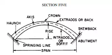
FIGURE 5.93 Components of an arch
The necessity of resisting the horizontal components of the reactions is an important consideration in arch design. Sometimes these forces are taken by the tie rods between the supports, sometimes by heavy abutments or buttresses.
Arches may be built with fixed ends, as can straight beams, or with hinges at the supports. They may also be built with a hinge at the crown.
Three-Hinged Arches
An arch with a hinge at the crown as well as at both supports (Fig. 5.94) is statically determinate. There are four unknowns—two horizontal and two vertical components of the reactions—but four equations based on the laws of equilibrium are available: (1) The sum of the horizontal forces must be zero. (2) The sum of the moments about the left support must be zero. (3) The sum of the moments about the right support must be zero. (4) The bending moment at the crown hinge must be zero (not to be confused with the sum of the moments about the crown, which also must be equal to zero, but which would not lead to an independent equation for the solution of the reactions).
Stresses and reactions in three hinged arches can be determined graphically by taking advantage of the fact that the bending moment at the crown hinge is zero. For example, in Fig. 5.94a, a concentrated load P is applied to segment AB of the arch. Then, since the bending moment at B must be zero, the line of action of the reaction at C must pass through the crown hinge. It intersects the line of action of P at X. The line of action of the reaction at A must also pass through X. Since P is equal to the sum of the reactions, and since the directions of the reactions have thus been determined, the magnitude of the reactions can be measured from a parallelogram of forces (Fig. 5.94b). When the reactions have been found, the stresses can be computed from the laws of statics or, in the case of a trussed arch, determined graphically.
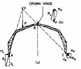
FIGURE 5.94 Three-hinged arch
Two-Hinged Arches When an arch has hinges at the supports only (Fig. 5.95), it is statically indeterminate, and some knowledge of its deformations is required to determine the reactions. One procedure is to assume that one of the supports is on rollers. This makes the arch statically determinate. The reactions and the horizontal movement of the support are computed for this condition (Fig. 5.95b). Then, the magnitude of the horizontal force required to return the movable support to its original position is calculated (Fig. 5.95c). The reactions for the two-hinged arch are finally found by superimposing the first set of reactions on the second (Fig. 5.95d).
For example, if  is the horizontal movement of the support due to the loads, and if
is the horizontal movement of the support due to a unit horizontal force applied to the support, then
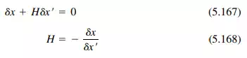
where H is the unknown horizontal reaction. (When a tie rod is used to take the thrust, the right-hand side of Eq. (5.167) is not zero, but the elongation of the rod, HL/AE.) The dummy unit-load method [Eq. (5.96)] can be used to compute  and .
and .
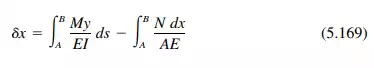
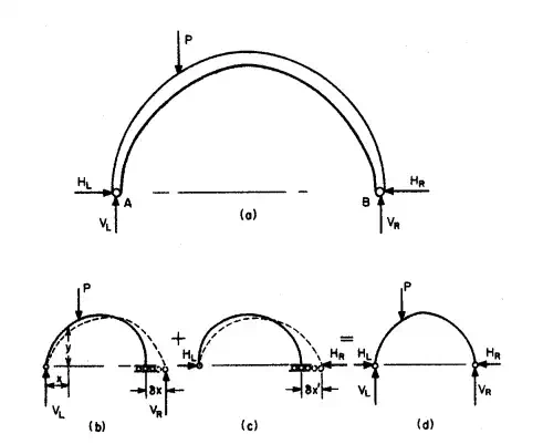
FIGURE 5.95 Two-hinged arch.
where
M = moment at any section resulting from loads
N = normal thrust on cross section
A = cross-sectional area of arch
y = ordinate of section measured from A as origin, when B is on rollers
I = moment of inertia of section
E = modulus of elasticity
ds = differential length along axis of arch
dx = differential length along horizontal.
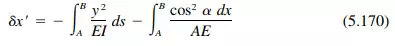
where  = the angle the tangent to the axis at the section makes with the horizontal. Unless the thrust is very large and would be responsible for large strains in the direction of the arch axis, the second term on the right-hand side of Eq. (5.169) can usually be ignored.
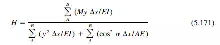
In most cases, integration is impracticable. The integrals generally must be evaluated by approximate methods. The arch axis is divided into a convenient number of sections and the functions under the integral sign evaluated for each section. The sum is approximately equal to the integral. Thus, for the usual two-hinged arch,
Stresses in Arch Ribs
When the reactions have been found for an arch, the principal forces acting on any cross section can be found by applying the equations of equilibrium. For example, consider the portion of an arch in Fig. 5.96, where the
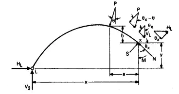
FIGURE 5.96 Interior stresses at X hold portion LX of an arch rib in equilibrium.
And the bending moment at X is

The shearing unit stress on the arch cross section at X can be determined from S with the aid of Eq. (5.59). The normal unit stresses can be calculated from N and M with the aid of Eq. (5.67).
In designing an arch, it may be necessary to compute certain secondary stresses, in addition to those caused by live, dead, wind, and snow loads. Among the secondary stresses to be considered are those due to temperature changes, rib shortening due to thrust or shrinkage, deformation of tie rods, and unequal settlement of footings. The procedure is the same as for loads on the arch, with the deformations producing the secondary stresses substituted for or treated the same as the deformations due to loads.