Buildings must be designed to resist horizontal forces as well as vertical loads. In tall buildings, the lateral forces must be given particular attention, because if they are not properly provided for, they can collapse the structure (Art. 3.2.3). The usual procedure for preventing such disasters is to provide structural framing capable of transmitting the horizontal forces from points of application to the building foundations.
Because the horizontal loads may come from any direction, they generally are resolved into perpendicular components, and correspondingly the lateral-force resisting framing is also placed in perpendicular directions. The maximum magnitude of load is assumed to act in each of those directions. Bents or shear walls, which act as vertical cantilevers and generally are often also used to support some of the building’s gravity loads, usually are spaced at appropriate intervals for transmitting the loads to the foundations.
A bent consists of vertical trusses or continuous rigid frames located in a plane. The trusses usually are an assemblage of columns, horizontal girders, and diagonal bracing. The rigid frames are composed of girders and columns, with so-called wind connections between them to establish continuity. Shear walls are thin cantilevers braced by floors and roofs.
Diaphragms
Horizontal distribution of lateral forces to bents and shear walls is achieved by the floor and roof systems acting as diaphragms (Fig. 5.81).
To qualify as a diaphragm, a floor or roof system must be able to transmit the lateral forces to bents and shear walls without exceeding a horizontal deflection that would cause distress to any vertical element. The successful action of a diaphragm also requires that it be properly tied into the supporting framing. Designers should ensure this action by appropriate detailing at the juncture between horizontal and vertical structural elements of the building.
Diaphragms may be considered analogous to horizontal (or inclined, in the case of some roofs) plate girders. The roof or floor slab constitutes the web; the joists, beams, and girders function as stiffeners; and the bents and shear walls act as flanges.
Diaphragms may be constructed of structural materials, such as concrete, wood, or metal in various forms. Combinations of such materials are also possible. Where a diaphragm is made up of units, such as plywood, precast-concrete planks, or steel decking, its characteristics are, to a large degree, dependent on the attachments of one unit to another and to the supporting members. Such attachments must resist shearing stresses due to internal translational and rotational actions.
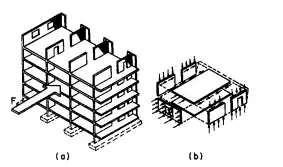
FIGURE 5.81 Floors of building distribute horizontal loads to shear walls (diaphragm action).
The stiffness of a horizontal diaphragm affects the distribution of the lateral forces to the bents and shear walls. For the purpose of analysis, diaphragms may be classified into three groups—rigid, semirigid or semiflexible, and flexible— although no diaphragm is actually infinitely rigid or infinitely flexible.
A rigid diaphragm is assumed to distribute horizontal forces to the vertical resisting elements in proportion to the relative rigidities of these elements (Fig. 5.82).
Semirigid or semiflexible diaphragms are diaphragms that deflect significantly under load but have sufficient stiffness to distribute a portion of the load to the vertical elements in proportion to the rigidities of these elements. The action is analogous to a continuous beam of appreciable stiffness on yielding supports (Fig. 5.83). Diaphragm reactions are dependent on the relative stiffnesses of diaphragm and vertical resisting elements.
A flexible diaphragm is analogous to a continuous beam or series of simple beams spanning between nondeflecting supports. Thus, a flexible diaphragm is considered to distribute the lateral forces to the vertical resisting elements in proportion to the exterior-wall tributary areas (Fig. 5.84).
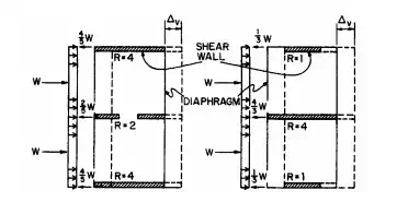
FIGURE 5.82 Horizontal section through shear walls connected by a rigid diaphragm. R relative rigidity and shear-wall v deflection.
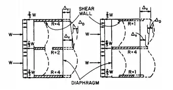
FIGURE 5.83 Horizontal sections through shear walls connected by a semirigid diaphragm. D diaphragm horizontal deflection.
A rigorous analysis of lateral-load distribution to shear walls or bents is sometimes very time-consuming, and frequently unjustified by the results. Therefore, in many cases, a design based on reasonable limits may be used. For example, the load may be distributed by first considering the diaphragm rigid, and then by considering it flexible. If the difference in results is not great, the shear walls can then be safely designed for the maximum applied load.
Torque Distribution to Shear Walls
When the line of action of the resultant of lateral forces acting on a building does not pass through the center of rigidity of a vertical, lateral-force-resisting system, distribution of the rotational forces must be considered as well as distribution of the transnational forces. If rigid or semirigid diaphragms are used, the designer may assume that torsional forces are distributed to the shear walls in proportion to their relative rigidities and their distances from the center of rigidity. A flexible diaphragm should not be considered capable of distributing torsional forces.
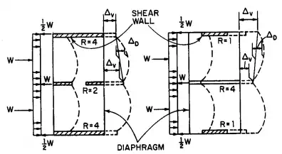
FIGURE 5.84 Horizontal section through shear walls connected by a flexible diaphragm.
Example of Torque Distribution to Shear Walls.
To illustrate load-distribution calculations for shear walls with rigid or semirigid diaphragms, Fig. 5.85 shows a horizontal section through three shear walls A, B, and C taken above a rigid floor. Wall B is 16 ft from wall A, and 24 ft from wall C. Rigidity of A 0.33, of B 0.22, and of C 0.45. A 20-kip horizontal force acts at floor level parallel to the shear walls and midway between A and C.
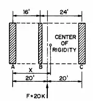
FIGURE 5.85 Rigid diaphragm distributes 20-kip horizontal force to shear walls A, B, and C.
The center of rigidity of the shear walls is located, relative to wall A, by taking moments about A of the wall rigidities and dividing the sum of these moments by the sum of the wall rigidities, in this case 1.00.
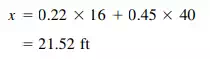
Thus, the 20-kip lateral force has an eccentricity of 21.52 – 20 = 1.52 ft. The eccentric force may be resolved into a 20-kip force acting through the center of rigidity and not producing torque, and a couple producing a torque of 20 x 1.52 = 30.4 ft-kips.
The nonrotational force is distributed to the shear walls in proportion to their rigidities:
· Wall A: 0.33 x 20 = 6.6 kips
· Wall B: 0.22 x 20 = 4.4 kips
· Wall C: 0.45 x 20 = 9.0 kips
For distribution of the torque to the shear walls, the equivalent of moment of inertia must first be computed:

Then, the torque is distributed in direct proportion to shear-wall rigidity and distance from center of rigidity and in inverse proportion to I.
· Wall A: 30.4 x 0.33 x 21.52/313 = 0.690 kips
· Wall B: 30.4 x 0.22 x 5.52/313 = 0.118 kips
· Wall C: 30.4 x 0.45 x 18.48/313 = 0.808 kips
The torsional forces should be added to the nonrotational forces acting on walls A and B, whereas the torsional force on wall C acts in the opposite direction to the nonrotational force. For a conservative design, the torsional force on wall C should not be subtracted. Hence, the walls should be designed for the following forces:
• Wall A: 6.6 + 0.7 = 7.3 kips
• Wall B: 4.4 + 0.1 = 4.5 kips
• Wall C: kips
Deflections of Bents or Shear Walls
When parallel bents or shear walls are connected by rigid diaphragms (Art. 5.12.1) and horizontal loads are distributed to the vertical resisting elements in proportion to their relative rigidities, the relative rigidity of the framing depends on the combined horizontal deflections due to shear and flexure. For the dimensions of lateral force-resisting framing used in many high-rise buildings, however, deflections due to flexure greatly exceed those due to shear. In such cases, only flexural rigidity need be considered in determination of relative rigidity of the bents and shear walls.
Horizontal deflections can be determined by treating the bents and shear walls as cantilevers. Deflections of braced bents can be calculated by the dummy-unit load method or a matrix method. Deflections of rigid frames can be obtained by summing the drifts of the stories, as determined by moment distribution or a matrix method. And deflections of shear walls can be computed from formulas given in , the dummy-unit-load method, or a matrix method.
For a shear wall with a solid, rectangular cross section, the flexural deflection at the top under uniform loading is given by the formula for a cantilever in Fig. 5.39:
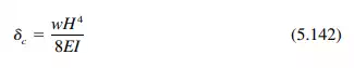
where w = uniform lateral load
H = height of the wall
E = modulus of elasticity of the wall material
I = moment of inertia of wall cross section tL3 /12
t = wall thickness
L = length of wall
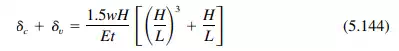
The cantilever shear deflection under uniform loading may be computed from
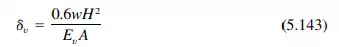
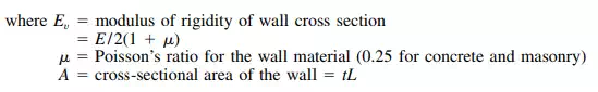
The total deflection then is
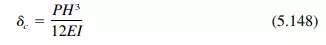
For a cantilever wall subjected to a concentrated load P at the top, the flexural deflection at the top is
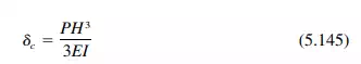
The shear deflection at the top of the wall is
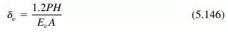
Hence, the total deflection of the cantilever is
For a wall fixed against rotation a the top and subjected to a concentrated load P at the top, the flexural deflection at the top is
The shear deflection for the fixed-end wall is given by Eq. (5.145). Hence, the total deflection for the wall is
Diaphragm-Deflection Limitations
Horizontal deflection of diaphragms plays an important role in determining lateral-load distribution to bents and shear walls. Another design consideration is the necessity of limiting diaphragm deflection to prevent excessive stresses in walls perpendicular to shear walls. Equation (5.150) was suggested by the Structural Engineers Association of Southern California for allowable story deflection , in, of masonry or concrete building walls.
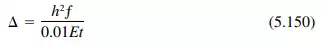
where
h = height of wall between adjacent horizontal supports, ft
t = thickness of wall, in
ƒ = allowable flexural compressive stress of wall material, psi
E = modulus of elasticity of wall material, psi
This limit on deflection must be applied with engineering judgment. For example, continuity of wall at floor level is assumed, and in many cases is not present because of through-wall flashing. In this situation, the deflection may be based on the allowable compressive stress in the masonry, if a reduced cross section of wall is assumed. The effect of reinforcement, which may be present in a reinforced brick masonry wall or as a tie to the floor system in a nonreinforced or partly reinforced masonry wall, was not considered in development of Eq. (5.150). Note also that the limit on wall deflection is actually a limit on differential deflection between two successive floor, or diaphragm, levels.
Maximum span-width or span-depth ratios for diaphragms are usually used to control horizontal diaphragm deflection indirectly. Normally, if the diaphragm is designed with the proper ratio, the diaphragm deflection will not be critical. Table 5.8 may be used as a guide for proportioning diaphragms.
Shear-Wall Rigidity
Where shear walls are connected by rigid diaphragms so that they must deflect equally under horizontal loads, the proportion of total horizontal load at any level carried by a shear wall parallel to the load depends on the relative rigidity, or stiffness, of the wall in the direction of the load. Rigidity of a shear wall is inversely proportional to its deflection under unit horizontal load. This de- flection equals the sum of the shear and flexural deflections under the load.
Where a shear wall contains no openings, computations for deflection and rigidity are simple. In Fig. 5.86a, each of the shear walls has the same length and rigidity. So each takes half the total load. In Fig. 5.86b, length of wall C is half that of wall D. By Eq. (5.142), C therefore receives less than one-eighth the total load.
Walls with Openings.
Where shear walls contain openings, such as doors and windows, computations for deflection and rigidity are more complex. But approximate methods may be used.
For example, the wall in Fig. 5.87, subjected to a 1000-kip load at the top, may be treated in parts. The wall is 8 in thick, and its modulus of elasticity E = 2400 ksi. Its height-length ratio H/L is 12⁄20 = 0.6. The wall is perforated by two, symmetrically located, 4-ft-square openings.
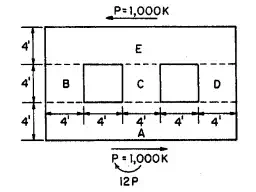
FIGURE 5.87 Shear wall, 8 in thick, with openings.
Deflection of this wall can be estimated by subtracting from the deflection it would have if it were solid the deflection of a solid, 4-ft-deep, horizontal midstrip, and then adding the deflection of the three coupled piers B, C, and D.
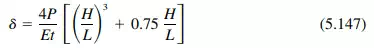
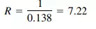
Deflection of the 12-ft-high solid wall can be obtained from Eq. (5.147):
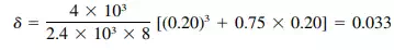
in Rigidity of the solid wall then is
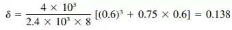
Similarly, the deflection of the 4-ft-deep solid midstrip can be computed from Eq. (5.147), with H/L = 4 ⁄20 = 0.20.
in Deflection of the piers, which may be considered fixed top and bottom, can be
TABLE 5.8 Maximum Span-Width or Span-Depth Ratios for diaphragms—Roofs or Floors*
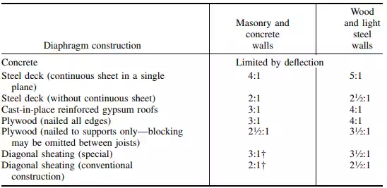
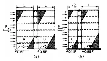
FIGURE 5.86 Distribution of horizontal load to parallel shear walls: (a) walls with the same length and rigidity share the load equally; (b) wall half the length of another carries less than one-eighth of the load.
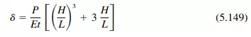
obtained from Eq. (5.149), with H/L = 4 ⁄4 = 1. For any one of the piers, the deflection is
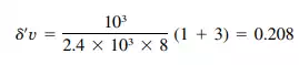 in
in
The rigidity of a single pier is 1/0.208 = 4.81, and of the three piers, 3 x 4.81 = 14.43. Therefore, the deflection of the three piers when coupled is
 in
in
The deflection of the whole wall, with openings, then is approximately
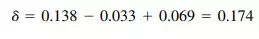 in
in
And its rigidity is
Effects of Shear-Wall Arrangements
To increase the stiffness of shear walls and thus their resistance to bending, intersecting walls or flanges may be used. Often in the design of buildings, A-, T-, U-, L-, and I-shaped walls in plan develop as natural parts of the design. Shear walls with these shapes have better flexural resistance than a single, straight wall.
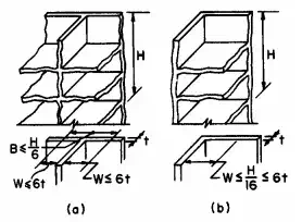
FIGURE 5.88 Effective flange width of shear walls may be less than the actual width: (a) limits for flanges of I and T shapes; (b) limits for C and L shapes.
In calculation of flexural stresses in masonry shear walls for symmetrical T or I section, the effective flange width may not exceed one-sixth the total wall height above the level being analysed. For unsymmetrical L or C sections, the width considered effective may not exceed one-sixteenth the total wall height above the level being analysed. In either case, the overhang for any section may not exceed six times the flange thickness (Fig. 5.88).
The shear stress at the intersection of the walls should not exceed the permissible shear stress.
Coupled Shear Walls
Another method than that described in Art. 5.12.6 for increasing the stiffness of a bearing-wall structure and reducing the possibility of tension developing in masonry shear walls under lateral loads is coupling of coplanar shear walls.
Figure 5.89 and 5.90 indicate the effect of coupling on stress distribution in a pair of walls under horizontal forces parallel to the walls. A flexible connection between the walls is assumed in Figs. 5.89a and 5.90a, so that the walls act as independent vertical cantilevers in resisting lateral loads. In Figs. 5.89b and 5.90b, the walls are assumed to be connected with a more rigid member, which is capable of shear and moment transfer. A rigid-frame type action results. This can be accomplished with a steel-reinforced concrete, or reinforced brick masonry coupling.
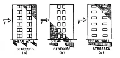
FIGURE 5.89 Stress distribution in end shear walls: (a) with flexible coupling; (b) with rigid-frame-type action; (c) with plate-type action.
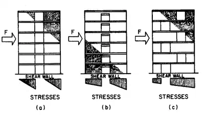
FIGURE 5.90 Stress distribution in interior shear walls: (a) with flexible coupling; (b) with rigid-frame-type action; (c) with plate-type action.
A plate-type action is indicated in Figs. 5.89c and 5.90c. This assumes an extremely rigid connection between walls, such as fully story-height walls or deep rigid spandrels.


Comments are closed.