A structural membrane or shell is a curved surface structure. Usually, it is capable of transmitting loads in more than two directions to supports. It is highly efficient structurally when it is so shaped, proportioned, and supported that it transmits the loads without bending or twisting.
A membrane or a shell is defined by its middle surface, halfway between its extrados, or outer surface and intrados, or inner surface. Thus, depending on the geometry of the middle surface, it might be a type of dome, barrel arch, cone, or hyperbolic paraboloid. Its thickness is the distance, normal to the middle surface, between extrados and intrados.
Thin-Shell Analysis
A thin shell is a shell with a thickness relatively small compared with its other dimensions. But it should not be so thin that deformations would be large compared with the thickness.
The shell should also satisfy the following conditions: Shearing stresses normal to the middle surface are negligible. Points on a normal to the middle surface before it is deformed lie on a straight line after deformation. And this line is normal to the deformed middle surface.
Calculation of the stresses in a thin shell generally is carried out in two major steps, both usually involving the solution of differential equations. In the first, bending and torsion are neglected. In the second step, corrections are made to the previous solution by superimposing the bending and shear stresses that are necessary to satisfy boundary conditions.
Ribbed Shells
For long-span construction, thin shells often are stiffened at intervals by ribs. Usually, the construction is such that the shells transmit some of the load imposed on them to the ribs, which then perform structurally as more than just stiffeners. Stress and strain distributions in shells and ribs consequently are complicated by the interaction between shells and ribs. The shells restrain the ribs, and the ribs restrain the shells. Hence, ribbed shells usually are analysed by approximate methods based on reasonable assumptions.
For example, for a cylindrical shell with circumferential ribs, the ribs act like arches. For an approximate analysis, the ribbed shell therefore may be assumed to be composed of a set of arched ribs with the thin shell between the ribs acting in the circumferential direction as flanges of the arches. In the longitudinal direction, it may be assumed that the shell transfers load to the ribs in flexure. Designers may adjust the results of a computation based on such assumptions to correct for a variety of conditions, such as the effects of free edges of the shell, long distances between ribs, relative flexibility of ribs and shell, and characteristics of the structural materials.
Membrane Theory for Thin Shells
Thin shells usually are designed so that normal shears, bending moments, and torsion are very small, except in relatively small portions of the shells. In the membrane theory, these stresses are ignored.
Despite the neglected stresses, the remaining stresses ae in equilibrium, except possibly at boundaries, supports, and discontinuities. At any interior point, the number of equilibrium conditions equals the number of unknowns. Thus, in the membrane theory, a thin shell is statically determinate.
The membrane theory does not hold for concentrated loads normal to the middle surface, except possibly at a peak or valley. The theory does not apply where boundary conditions are incompatible with equilibrium. And it is in exact where there is geometric incompatibility at the boundaries. The last is a common condition, but the error is very small if the shell is not very flat. Usually, disturbances of membrane equilibrium due to incompatibility with deformations at boundaries, supports, or discontinuities are appreciable only in a narrow region about each source of disturbance. Much larger disturbances result from incompatibility with equilibrium conditions.
To secure the high structural efficiency of a thin shell, select a shape, proportions, and supports for the specific design conditions that come as close as possible to satisfying the membrane theory. Keep the thickness constant; if it must change, use a gradual taper. Avoid concentrated and abruptly changing loads. Change curvature gradually. Keep discontinuities to a minimum. Provide reactions that are tangent to the middle surface. At boundaries, ensure, to the extent possible, compatibility of shell deformations with deformations of adjoining members, or at least keep restraints to a minimum. Make certain that reactions along boundaries are equal in magnitude and direction to the shell forces there.
Means usually adopted to satisfy these requirements at boundaries and supports are illustrated in Fig. 5.97. In Fig. 5.97a, the slope of the support and provision for movement normal to the middle surface ensure a reaction tangent to the middle surface. In Fig. 5.97b, a stiff rib, or ring girder, resists unbalanced shears and
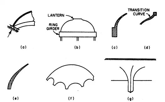
FIGURE 5.97 Special provisions made at supports and boundaries of thin shells to meet requirements of the membrane theory include: (a) a device to ensure a reaction tangent to the middle surface; (b) stiffened edges, such as the ring girder at the base of a dome; (c) gradually increased shell thicknesses at a stiffening member; (d) a transition curve at changes in section; (e) a stiffening edge obtained by thickening the shell; ( ƒ ) scalloped edges; (g) a flared support.
transmits normal forces to columns below. The enlarged view of the ring girder in Fig. 5.97c shows gradual thickening of the shell to reduce the abruptness of the change in section. The stiffening ring at the lantern in Fig. 5.97d, extending around the opening at the crown, projects above the middle surface, for compatibility of strains, and connects through a transition curve with the shell; often, the rim need merely be thickened when the edge is upturned, and the ring can be omitted. In Fig. 5.97e, the boundary of the shell is a stiffened edge. In Fig. 5.97f, a scalloped shell provides gradual tapering for transmitting the loads to the supports, at the same time providing access to the shell enclosure. And in Fig. 5.97g, a column is flared widely at the top to support a thin shell at an interior point. Even when the conditions for geometric compatibility are not satisfactory, the membrane theory is a useful approximation. Furthermore, it yields a particular solution to the differential equations of the bending theory.
Bending Theory for Thin Shells
When equilibrium conditions are not satisfied, or incompatible deformations exist at boundaries, bending and torsion stresses arise in the shell. Sometimes, the design of the shell and its supports can be modified to reduce or eliminate these stresses. When the design cannot eliminate them, provisions must be made for the shell to resist them.
But even for the simplest types of shells and loading, the stresses are difficult to compute. In bending theory, a thin shell is statically indeterminate; deformation conditions must supplement equilibrium conditions in setting up differential equations for determining the unknown forces and moments. Solution of the resulting equations may be tedious and time-consuming, if indeed solution if possible.
In practice, therefore, shell design relies heavily on the designer’s experience and judgment. The designer should consider the type of shell, material of which it is made, and support and boundary conditions, and then decide whether to apply a bending theory in full, use an approximate bending theory, or make a rough estimate of the effects of bending and torsion. (Note that where the effects of a disturbance are large, these change the normal forces and shears computed by the membrane theory.) For concrete domes, for example, the usual procedure is to use as support a deep, thick girder or a heavily reinforced or prestressed tension ring, and the shell is gradually thickened in the vicinity of this support (Fig. 5.97c).
Circular barrel arches, with ratio of radius to distance between supporting arch ribs less than 0.25 may be designed as beams with curved cross section. Secondary stresses, however, must be taken into account. These include stresses due to volume change of rib and shell, rib shortening, unequal settlement of footings, and temperature differentials between surfaces.
Stresses in Thin Shells
The results of the membrane and bending theories are expressed in terms of unit forces and unit moments, acting per unit of length over the thickness of the shell. To compute the unit stresses from these forces and moments, usual practice is to assume normal forces and shears to be uniformly distributed over the shell thickness and bending stresses to be linearly distributed.
Then, normal stresses can be computed from equations of the form
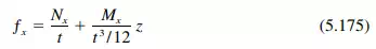
where z = distance from middle surface
t = shell thickness
Mx = unit bending moment about axis parallel to direction of unit normal force Nx
Similarly, shearing stresses produced by central shears and twisting moments may be calculated from equations of the form
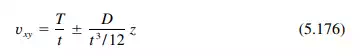
where D = twisting moment and T = unit shear force along the middle surface. Normal shearing stresses may be computed on the assumption of a parabolic stress distribution over the shell thickness:
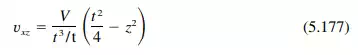
where V unit shear force normal to middle surface.
Folded Plates
A folded-plate structure consists of a series of thin planar elements, or flat plates, connected to one another along their edges. Usually used on long spans, especially for roofs, folded plates derive their economy from the girder action of the plates and the mutual support they give one another.
Longitudinally, the plates may be continuous over their supports. Transversely, there may be several plates in each bay (Fig. 5.98). At the edges, or folds, they may be capable of transmitting both moment and shear or only shear.
A folded-plate structure has a two-way action in transmitting loads to its supports. Transversely, the elements act as slabs spanning between plates on either side. The plates then act as girders in carrying the load from the slabs longitudinally to supports, which must be capable of resisting both horizontal and vertical forces.
If the plates are hinged along their edges, the design of the structure is relatively simple. Some simplification also is possible if the plates, though having integral edges, are steeply sloped or if the span is sufficiently long with respect to other dimensions that beam theory applies. But there are no criteria for determining when such simplification is possible with acceptable accuracy. In general, a reasonably accurate analysis of folded-plate stresses is advisable.
The material is elastic, isotropic, and homogeneous. The longitudinal distribution of all loads on all plates is the same. The plates carry loads transversely only by bending normal to their planes and longitudinally only by bending within their planes. Longitudinal stresses vary linearly over the depth of each plate. Supporting members, such as diaphragms, frames, and beams, are infinitely stiff in their own planes and completely flexible normal to their own planes. Plates have no torsional stiffness normal to their own planes. Displacements due to forces other than bending moments are negligible.
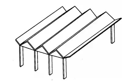
FIGURE 5.98 Folded-plate structure
Regardless of the method selected, the computations are rather involved; so it is wise to carry out the work by computer or, when done manually, in a well-organized table. The Yitzhaki method offers some advantages over others in that the calculations can be tabulated, it is relatively simple, it requires the solution of no more simultaneous equations than one for each edge for simply supported plates, it is flexible, and it can easily be generalized to cover a variety of conditions.
Yitzhaki Method.
Based on the assumptions and general procedure given above, the Yitzhaki method deals with the slab and plate systems that comprise a folded plate structure in two ways. In the first, a unit width of slab is considered continuous over supports immovable in the direction of the load (Fig. 5.99b). The strip usually is taken where the longitudinal plate stresses are a maximum. Second, the slab reactions are taken as loads on the plates, which now are assumed to be hinged along the edged (Fig. 5.99c). Thus, the slab reactions cause angle changes in the plates at each fold. Continuity is restored by applying to the plates an unknown moment at each edge. The moments can be determined from the fact that at each edge the sum of the angle changes due to the loads and to the unknown moments must equal zero.
The angle changes due to the unknown moments have two components. One is the angle change at each slab end, now hinged to an adjoining slab, in the transverse strip of unit width. The second is the angle change due to deflection of the plates. The method assumes that the angle change at each fold varies in the same way longitudinally as the angle changes along the other folds. For example, for the folded-plate structure in Fig. 5.99a, the steps in analysis are as follows:
Step 1. Compute the loads on a 12-in-wide transverse strip at midspan.
Step 2. Consider the strip as a continuous slab supported at the folds (Fig. 5.99b) and compute the bending moments by moment distribution.
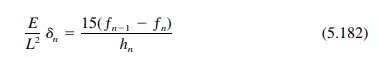
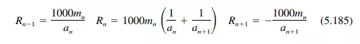
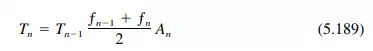
Step 3. From the end moments M found in Step 2, compute slab reactions and plate loads. Reactions (positive upward) at the nth edge are
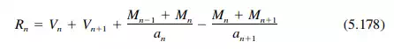
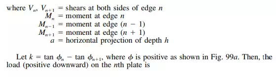
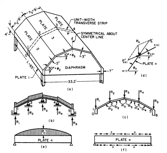
FIGURE 5.99 Folded plate is analysed by first considering a transverse strip (a) as a continuous slab on supports that do not settle (b). then, (c) the slabs are assumed hinged and acted upon by the reactions computed in the first step and by unknown moments to correct for this assumption. (d) Slab reactions are resolved into plate forces, parallel to the planes of the plates. (e) In the longitudinal direction, the plates act as deep girders with shears along the edges. ( ƒ ) Arrows indicate the positive directions for the girder shears.
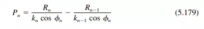
(Figure 5.99d shows the resolution of forces at edge n; n = 1 is similar.) Equation (5.179) does not apply for the case of a vertical reaction on a vertical plate, for R/k is the horizontal component of the reaction.
Step 4. Calculate the midspan (maximum) bending moment in each plate. In this example, each plate is a simple beam and M = PL2 /8, where L is the span in feet.
Step 5. Determine the free-edge longitudinal stresses at midspan. In each plate, these can be computed from
where ƒ is the stress in psi, M the moment in ft-lb from Step 4, A plate cross-sectional area and tension is taken as positive, compression as negative.
Step 6. Apply a shear to adjoining edges to equalize the stresses there. Compute the adjusted stresses by converging approximations, similar to moment distribution. To do this, distribute the unbalanced stress at each edge in proportion to the reciprocals of the areas of the plates, and use a carry-over factor of -1 ⁄2 to distribute the tress to a far edge. Edge 0, being a free edge, requires no distribution of the stress there. Edge 3, because of symmetry, may be treated the same, and distribution need be carried out only in the left half of the structure.
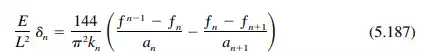
Step 7. Compute the midspan edge deflections. In general, the vertical component can be computed from
where E = modulus of elasticity, psi
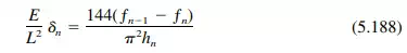
The factor  is retained for convenience; it is eliminated by dividing the simultaneous angle equations by it. For a vertical plate, the vertical deflection is given by
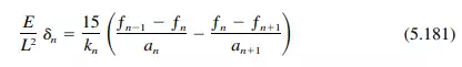
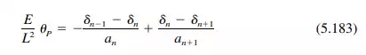
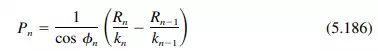
Step 8. Compute the midspan angle change P at each edge. This can be determined from
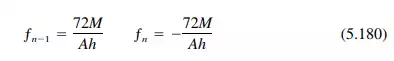
Step 10. Compute the slab reactions and plate loads due to the unknown moments. The reactions are
The plate loads are
Step 11. Assume that the loading on each plate is  (Fig. 5.99e) and calculate the midspan (maximum) bending moment. For a simple beam,

Step 12. Using Eq. (5.180), compute the free-edge longitudinal stresses at midspan. Then, as in Step 6, apply a shear at each edge to equalize the stresses. Determine the adjusted stresses by converging approximations.
Step 13. Compute the vertical component of the edge deflections at midspan from
or for a vertical plate from
In the example, To 0, so the shears at the edges can be obtained successively, since the stresses ƒ are known.
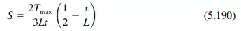
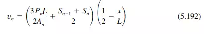
For a uniformly loaded folded plate, the shear stress S, psi, at any point on an edge n is approximately
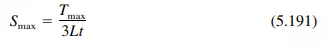
With a maximum at plate ends of
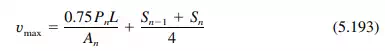
The shear stress, psi, at middepth (not always a maximum) is
and has its largest value at x 0:


Comments are closed.