Columns are compression members whose cross-sectional dimensions are relatively small compared with their length in the direction of the compressive force. Failure of such members occurs because of instability when a certain axial load Pc (called critical or Euler load) is equated or exceeded. The member may bend, or buckle, suddenly and collapse.
Hence the strength P of a column is not determined by the unit stress in Eq. (5.21) (P Aƒ) but by the maximum load it can carry without becoming unstable. The condition of instability is characterized by disproportionately large increases in lateral deformation with slight increase in axial load. Instability may occur in slender columns before the unit stress reaches the elastic limit.
Stable Equilibrium
Consider, for example, an axially loaded column with ends unrestrained against rotation, shown in Fig. 5.43. If the member is initially perfectly straight, it will remain straight as long as the load P is less than the critical load Pc. If a small transverse force is applied, the column will deflect, but it will return to the straight position when this force is removed. Thus, when P is less than Pc, internal and external forces are in stable equilibrium.
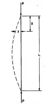
FIGURE 5.43 Buckling of a pin-ended long column.
Unstable Equilibrium
If P = Pc and a small transverse force is applied, the column again will deflect, but this time, when the force is removed, the column will remain in the bent position (dashed line in Fig. 5.43).
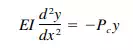 (5.87)
in which
E = modulus of elasticity
I = least moment of inertia
y = deflection of the bent member from the straight position at a distance x from one end
This assumes, of course, that the stresses are within the elastic limit. Solution of Eq. (5.87) gives the smallest value of the Euler load as
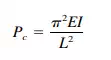 (5.88)
Equation (5.88) indicates that there is a definite finite magnitude of an axial load that will hold a column in equilibrium in the bent position when the stresses are below the elastic limit. Repeated application and removal of small transverse forces or small increases in axial load above this critical load will cause the member to fail by buckling. Internal and external forces are in a state of unstable equilibrium.
It is noteworthy that the Euler load, which determines the load-carrying capacity of a column, depends on the stiffness of the member, as expressed by the modulus of elasticity, rather than on the strength of the material of which it is made.
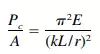
By dividing both sides of Eq. (5.88) by the cross-sectional area A and substituting r 2 for I/A (r is the radius of gyration of the section), we can write the solution of Eq. (5.87) in terms of the average unit stress on the cross section:
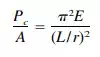 (5.89)
This holds only for the elastic range of buckling; i.e. for values of the slenderness ratio L/r above a certain limiting value that depends on the properties of the material.
Effect of End Conditions
Equation (5.89) was derived on the assumption that the ends of the column are free to rotate. It can be generalized, however, to take into account the effect of end conditions:
 (5.90)
where k is the factor that depends on the end conditions. For a pin-ended column,
k = 1; for a column with both ends fixed,
k = 1 ⁄2; for a column with one end fixed and one end pinned,
k is about 0.7; and for a column with one end fixed and one end free from all restraint,
k = 2.
Inelastic Buckling
Equations (5.88) and (5.90) are derived from Eq. (5.87), the differential equation for the elastic curve. They are based on the assumption that the critical average stress is below the elastic limit when the state of unstable equilibrium is reached. In members with slenderness ratio L/r below a certain limiting value, however, the elastic limit is exceeded before the column buckles. As the axial load approaches the critical load, the modulus of elasticity varies with the stress. Hence Eqs. (5.88) and (5.90), based on the assumption that E is a constant, do not hold for these short columns.
After extensive testing and analysis, prevalent engineering opinion favours the Engesser equation for metals in the inelastic range:
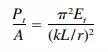 (5.91)
This differs from Eqs. (5.88) to (5.90) only in that the tangent modulus Et (the actual slope of the stress-strain curve for the stress Pt /A) replaced the modulus of elasticity E in the elastic range. Pt is the smallest axial load for which two equilibrium positions are possible, the straight position and a deflected position.
Column Curves
Curves obtained by plotting the critical stress for various values of the slenderness ratio are called column curves. For axially loaded, initially straight columns, the column curve consists of two parts: (1) the Euler critical values, and (2) the Engesser, or tangent-modulus critical values.
The latter are greatly affected by the shape of the stress-strain curve for the material of which the column is made, as shown in Fig. 5.44. The stress-strain curve for a material, such as an aluminium alloy or high-strength steel, which does not have a sharply defined yield point, is shown in Fig. 5.44a. The corresponding
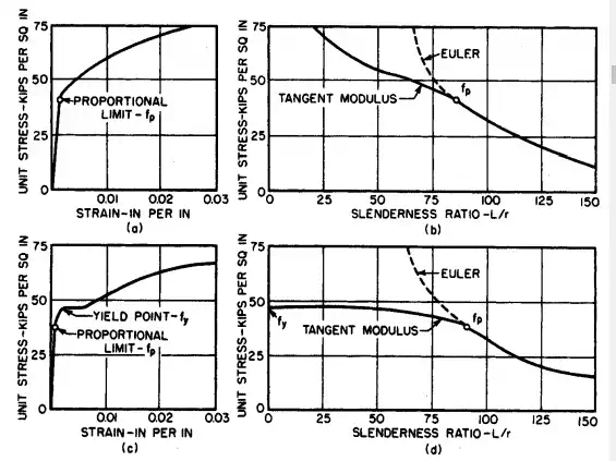
FIGURE 5.44 Column curves: (a) stress-strain curve for a material that does not have a sharply defined yield point: (b) column curve for this material; (c) stress-strain curve for a material with a sharply defined yield point; (d) column curve for that material.
column curve is drawn in Fig. 5.44b. In contrast, Fig. 5.44c presents the stress strain curve for structural steel, with a sharply defined point, and Fig. 5.44d the related column curve. This curve becomes horizontal as the critical stress approaches the yield strength of the material and the tangent modulus becomes zero, whereas the column curve in Fig. 5.44b continues to rise with decreasing values of the slenderness ratio.
Examination of Fig. 44d also indicates that slender columns, which fall in the elastic range, where the column curve has a large slope, are very sensitive to variations in the factor k, which represents the effect of end conditions. On the other hand, in the inelastic range, where the column curve is relatively flat, the critical stress is relatively insensitive to changes in k. Hence the effect of end conditions on the stability of a column is of much greater significance for long columns than for short columns.
Local Buckling
A column may not only fail by buckling of the member as a whole but as an alternative, by buckling of one of its components. Hence, when members like I beams, channels, and angles are used as columns or when sections are built up of plates, the possibility of the critical load on a component (leg, half flange, web, lattice bar) being less than the critical load on the column as a whole should be investigated.
Similarly, the possibility of buckling of the compression flange or the web of a beam should be looked into.
Local buckling, however, does not always result in a reduction in the load carrying capacity of a column. Sometimes, it results in a redistribution of the stresses enabling the member to carry additional load.
Behaviour of Actual Columns
For many reasons, columns in structures behave differently from the ideal column assumed in deriving Eqs. (5.88) and (5.91). A major consideration is the effect of accidental imperfections, such as non-homogeneity of materials, initial crookedness, and unintentional eccentricities of the axial load, since neither field nor shop work can be perfect. These and the effects of residual stresses usually are taken into account by a proper choice of safety factor.
There are other significant conditions, however, that must be considered in any design rule: continuity in frame structures and eccentricity of the axial load. Continuity affects column action in two ways. The restraint at column ends determines the value of k, and bending moments are transmitted to the column by adjoining structural members.
Because of the deviation of the behaviour of actual columns from the ideal, columns generally are designed by empirical formulas. Separate equations usually are given for short columns, intermediate columns, and long columns.