The structure that is planned to be built is described by using lines, symbols and notes in architectural drawings. This method is a universal language of describing a structure to be built and are called as Drafting.
Lines can be considered as the most expressive aspect when dealing with working drawings. Every line that is used in the drawing must have certain significance or else there won’t exist no significance in its existence.
The significance of the lines is mostly conveyed through the thickness of the line. If the thickness of the line is thin, it is less significant. If the line width is thick, it is more significant.
Before drawing a line, its significance must be kept it mind. This can come only through practice. This principle is followed and exercised in the CAD drawings too (Computer aided drafting).
Certain lines in the drawing are drawn very thick so that they clearly bear other unique form of information on the drawing. Other lines are drawn thin, which will convey other information.
Thin lines when compared with the thick lines are not necessarily less important. But the thin lines are subordinate lines compared with thick ones for the means of identification.
Outlines Used in Architectural Drawings
The outline lines are employed in the architectural drawings to define the outline as well as the characteristic features of the plan components of the architecture. This method of presentation varies with different office.
There are different alternatives that are used for outline presentation in architectural drawings, which are mentioned below:
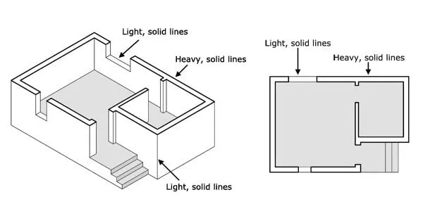
1. One main alternative is by employing a style of enhancing the main and important feature of the drawing under consideration, so that it clearly will stand out from other elements in the drawing.
For example, as shown in the figure-1, the floor plan wall outlines or the outlines of the partitions and beam cross section can be made thicker while drafting. This makes them different from other normal thin lines used in the drawing.
Fig.1: Thick Lines Used in Architectural Drawings
2. Another method is by drawing all the lines of same thickness. This method won’t bring any kind of differentiation between the elements of the drawing. All lines look the same.
This technique is used where the accentuate features like the wall in the floor plans can be provided with dark shading. The figure-2 below shows the drawing done by this method.
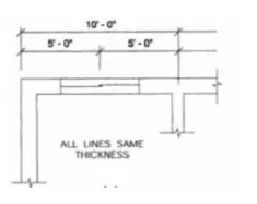
Fig.2: An architectural drawing where all lines are of same thickness


Fig.3: An architectural drawing provided with shading for the accentuate features (wall)
Dashed Lines in Architectural Drawings
To represent and show those features that are not visible or have no relationship with the view of the plan dashed lines are used in the architectural drawings. These dashed lines used are subordinate to the main features of the drawings.
Some of the features where the dashed lines are used are the beams and the headers as shown in figure-4, electrical circuit runs as shown in figure-5.
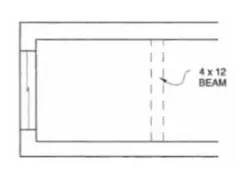

Fig.4: The dashed line is used to represent the beam and the header above.
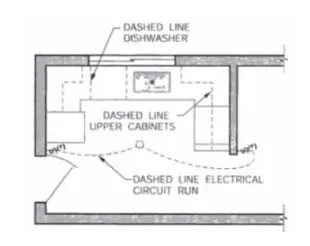

Fig.5: The above drawing uses dashed lines in order to represent the electric circuit lines, upper cabinets in the kitchen as well as the dishwasher


Comments are closed.