The dimension lines are used in the drawing to show the length of the dimension. The extension lines show how long the dimension extent.
The dimension lines terminate at the respected extension lines. This termination is represented by means of slashes, dots or arrowheads.
The dimension may be numeral in feet, millimeters or inches that will be placed above and near the center of the solid dimension of the line.
The figure-6 shows several examples of the dimension and the extension lines.
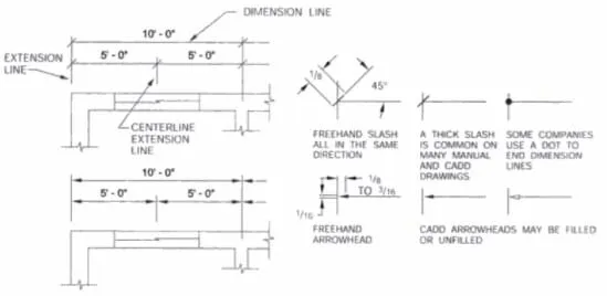
Fig.6: Drawing showing the use of dimension lines and the extension lines
Leader Lines
In order to connect the notes that is related to certain features in the drawing, leader lines are used. The figure -7 shows several examples:
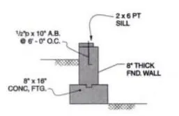
Fig.7: The sample figure showing the use of leader lines to explain the footing and the wall details
Break Lines
There are two types of break lines. One is the long break line and the other is the short break line. The long break line is the type of line that is associated with the architectural drafting.
To terminate a feature on the drawing, after the clear definition of the feature extend, break lines can be used. The figure-8 shows several examples of the of long and short break lines
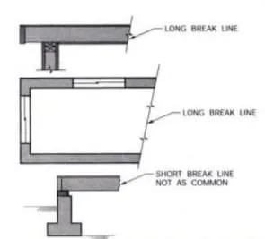
Fig.8: Use of short and long break lines in structural drawings
The short break lines are used in some drawings of structures. The lines that are shown in figure-8 are irregular lines which are mostly used in shorter areas.
The figure-9 shows the use of break lines inn cylindrical objects. The steel bars and pipes comes under this category.
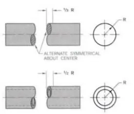
Fig.9. Break lines used in cylindrical and tubular objects


Comments are closed.