A floor plan is carefully dimensioned to ensure that items such as walls, columns, doors, windows, openings, stairs, and other particulars are correctly located for construction. Sometimes after a plan is drawn accurately to a scale, its reproduction causes a slight enlargement or reduction of the drawing. In such cases, the floor plan is slightly out of true scale, but this is acceptable because the written dimensions are the controlling factors. In fact, most designers add a note on the drawing that says, “do not scale drawing, follow written dimensions.”
Generally, elements such as walls are dimensioned to the frame (Figure 6-32), as the builder first erects this and then adds the finishes to it. This dimensioning technique gives the exact location of the studs, columns, and beams and is generally placed to the face of these. In some cases, however, the centerline of the wall might be located and dimensioned, as illustrated in Figure 6-33.
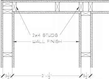
Figure 6-31 A portion of a floor plan can be keyed with a symbol to a larger, more detailed plan that is drawn elsewhere. For example, this part of the plan is referenced as area 6 and enlarged on sheet A4.
Figure 6-32 Dimensions on a floor plan generally locate the framework of the building, such as the face of these 2×4 studs.
As noted in Chapter 5, dimensioning is done in a hierarchical manner. Buildings, structural framework, rooms, and fixtures are dimensioned in decreasing size order. The actual number of dimensions on a plan is dependent upon how much latitude the designer affords the contractor. A very detailed and dimensioned plan gives the builder little room for deviation from the original design. However, if only a few key dimensions are shown, the builder is trusted to determine exact locations of interior components. A good guideline for dimensioning falls somewhere between these two approaches. An overdimensioned plan allows the builder little freedom to make field adjustments or substitute cost-saving techniques. However, too few dimensions can produce a lot of guesswork and increase the chances for error in the field and in coordination between subcontractors.
Figure 6-31 A portion of a floor plan can be keyed with a symbol to a larger, more detailed plan that is drawn elsewhere. For example, this part of the plan is referenced as area 6 and enlarged on sheet A4.
Figure 6-32 Dimensions on a floor plan generally locate the framework of the building, such as the face of these 2×4 studs.
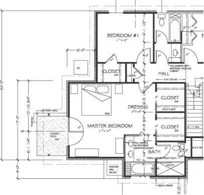
Figure 6-33 All dimensions in this floor plan are to the face of a stud, except for the wall between the closets. It is dimensioned to the centerline of the wall. The cen-terline technique can also be used to locate exterior windows and doors, as seen in this example.
Figure 6-33 All dimensions in this floor plan are to the face of a stud, except for the wall between the closets. It is dimensioned to the centerline of the wall. The cen-terline technique can also be used to locate exterior windows and doors, as seen in this example.
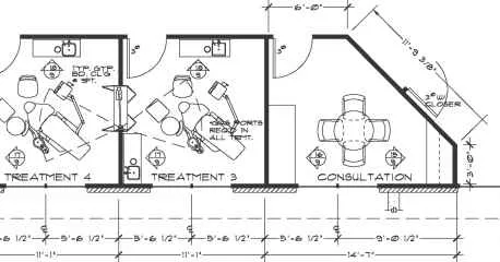
Figure 6-34 Note that the dimensions on this partial floor plan are placed outside of the spaces. The extension lines do not touch the walls, and dark 45-degree tick marks indicate the extent of the dimensions.
Dimensioning Techniques
Dimensions are placed on the floor plan as shown in Figure 6-34. Note that the dimension lines are drafted lighter than wall lines and are generally done as a continuous group or string of numbers along a line. The extension line begins slightly away from the object (a minimum of Vi6 inch or 1.58 mm), never touching it. It extends about V8 inch (3.17 mm) beyond the dimension line. Arrows, dots, or 45-degree tick marks (most common) are used at the extension line and dimension line junction (Figure 6-35). The arrows, dots, or tick marks are drawn with a thicker and/or darker line to make them stand out graphically. The 45-degree tick marks are drawn in a consistent direction. However, some draftspersons slope the tick marks for vertically read dimensions from left to right and horizontally read dimensions from right to left. When using the computer, any of these three graphic symbols (arrows, dots, or ticks) can be called up and consistently inserted for all dimensions.
Dimensioning on a floor plan usually requires two or three continuous dimension lines to locate exterior walls, wall jogs, interior walls, windows, doors, and other elements, as shown in Figure 6-36. Exterior walls of a building are dimensioned outside the floor plan. The outermost dimension line is the overall building dimension. The next dimension line, moving toward the plan, indicates wall locations and centerlines to doors and windows. Other miscellaneous details in the plan (such as minor offsets, jogs, or cabinetry and fixtures) are located on a third dimension line. This hierarchy of line work allows the carpenters and other trades to quickly locate major framing elements and minor details by referring to the appropriate dimension line.
BAR STOOLS
30VS4′ SOFA END TABLE
BAR STOOLS
30VS4′ SOFA END TABLE
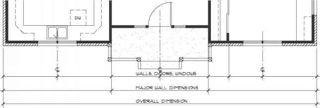
Figure 6-36 Dimensioning on a floor plan is grouped hierarchically, working from the overall dimension of the exterior walls to the smaller components of a building or space, such as wall jogs, interior walls, windows, doors, and other important elements.
Figure 6-35 Dark tick marks at 45 degrees to a dimension’s extension line are the most common technique for indicating junction points.
Figure 6-36 Dimensioning on a floor plan is grouped hierarchically, working from the overall dimension of the exterior walls to the smaller components of a building or space, such as wall jogs, interior walls, windows, doors, and other important elements.
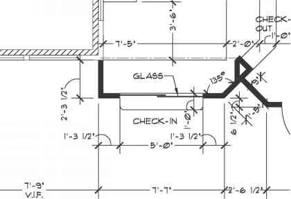
Figure 6-37 A leader is used to indicate the distance of 1′-3J’2″ from a wall corner to the check-in shelf on this partial plan, as the space within the dimension line is too small to letter in.
Figure 6-38 Floor plans in small residential projects often depict material finishes, such as this tiled floor in the entry, kitchen, breakfast area, and utility room.


Comments are closed.