Orthographic projection is a technique for drawing a three dimensional object in two dimensions, by ‘projecting’ its surfaces into a two dimensional representation, where the projection lines are orthogonal to (perpendicular to) the projection plane (that is, there is no foreshortening or perspective).
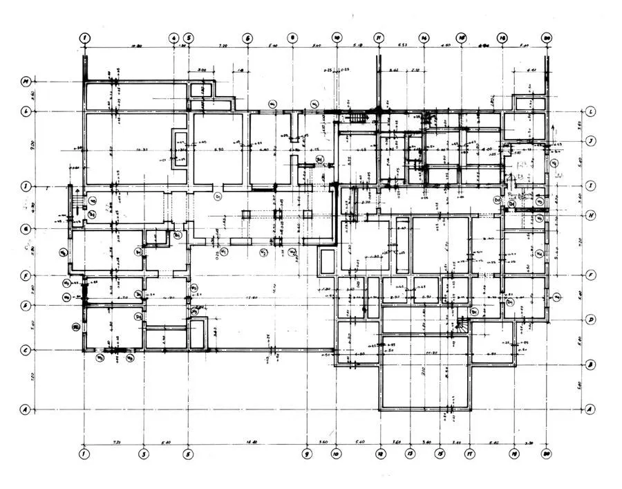
Floor plans are a form of orthographic projection that can be used to show the layout of rooms within buildings, as seen from above. They may be prepared as part of the design process, or to provide instructions for construction, often associated with other drawings, schedules, and specifications.
Floor plans may include key dimensions and levels, and may also use, hatching, symbols and other standard annotations and abbreviations to indicate materials, fittings and appliances, and so on.
Depending on the size of the building, floor plans are typically drawn at scales of between 1:200 and 1:20. Different line types, colours and weights can be used to differentiate between the types of drawn information they include.
Floor plans can be drawn for whole buildings, a single floor of a building, or just a single room. The more detailed the floor plan is in terms of layout, fittings and so on, the more useful and instructive it will be for the project. However, if spaces are complex, it is normal for separate drawings to be prepared for different trades, such as electrical and lighting drawings, plumbing drawings, and so on.
The lower-right-hand corner of the sheet is typically reserved for a title block. This provides a space to record the name of the project, the name of the drawing, the scale, the originators name, the date, revision history, and so on.
The floor plan view should be roughly centred on the sheet, with the front of the building typically drawn along the lower side of the sheet. A north point may be included to show the orientation of the floor plan.
Typically, the outside walls are drawn first, to lay the plan out on the sheet, then the internal walls, then windows, doors, stairs, lifts, ramps, and so on, are added. An arrow is used to indicate the upward direction of stairs and ramps. It is usual for a faint dotted line to be drawn around stairs (or other openings) where they are open at ceiling level.
Rooms should be clearly labelled, with block lettering in the centre of each room. The correct symbols should be added for elements such as; appliances, fixed furniture, fittings, building services, and so on.
Electrical symbols should be added to the drawing, indicating; power sockets, light switches, wall and ceiling lights, detectors and alarms, extract fans, and so on.
Items that are ceiling mounted, are generally drawn on the floor below their place of installation.
Dimension may be added to indicate the size and location of key elements such as; rooms, fittings, appliances or fixtures, external walls, window and door openings, and so on.
Section lines may be added where there are section drawings associated with the floor plan. Grid references may also be added to help co-ordinate the floor plan with other drawings.
Some floor plans may include notional furniture to help gauge the likely size of circulation spaces.
If a window or door schedule is to be prepared, doors and windows may be labelled with a number or letter, corresponding to an item on the schedule.
Floor plans should not duplicate information that is presented in specifications or schedules because of the potential for conflict. Instead they should refer to the specification or schedule.


Comments are closed.