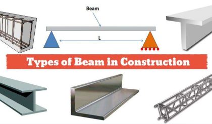
A structural member loaded axially in compression is generally called a compression member. Vertical compression members in buildings are called columns, posts or stanchions. A compression member in roof trusses is called struts and in a crane is called a boom.
Columns which are short are subjected to crushing and behave like members under pure compression. Columns which are long tend to buckle out of the plane of the load axis.
THEORY OF COLUMNS
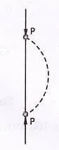
Euler’s formula for critical load for a pin-ended column subjected to axial load is
Where, L = length of column between the hinged ends,
E = modulus of elasticity, and
I = moment of inertia of the column section.
The column will become unserviceable if the loads are larger than ![]() . In the Euler equation, it is assumed that stress is proportional to strain, therefore,
. In the Euler equation, it is assumed that stress is proportional to strain, therefore,
Critical Stress =
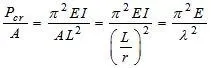
Where, A= area of cross-section, and
r = radius of gyration about the bending axis
![]() = slenderness ratio
= slenderness ratio
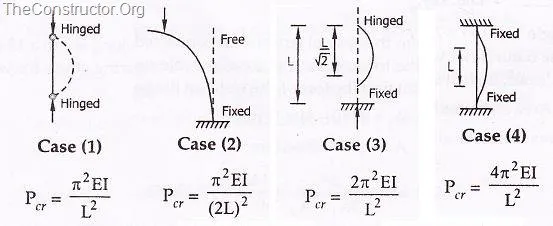
VARIOUS END CONDITIONS
Columns with length L and effective length ![]() are shown in figure below:
are shown in figure below:
Strength of an Axially Loaded Compression Members
Maximum axial compression load permitted on a compression member,

Where, P = axial compressive load (N),
![]() = permissible stress in axial compression (MPa)
= permissible stress in axial compression (MPa)
A = effective cross-sectional area of the member 
Indian Standard IS 800: 1984
It stipulates that the direct stress on the cross-sectional area of axially loaded compression members should not exceed ![]() nor the permissible stress calculated using Merchant – Rankine formula.
nor the permissible stress calculated using Merchant – Rankine formula.
Permissible stress in axial compression (MPa):
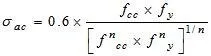
Where ![]() = yield stress of steel in MPa
= yield stress of steel in MPa
![]() = elastic critical stress in compression =
= elastic critical stress in compression = ![]()
![]() = slenderness ratio of the member
= slenderness ratio of the member
Where, ![]() = effective length of the member
= effective length of the member
r = appropriate radius of gyration of the member
E = modulus of elasticity = 200000 MPa, and
n = a factor assumed as 1.4
EFFECTIVE LENGTH OF COMPRESSION MEMBER
Table below gives the values of effective length recommended by the Indian Standard, IS 800. The actual length L of the compression member should be taken as the length from centre-to-centre of intersection of supporting members or the cantilevered length in the case of free standing struts.
Table: Equivalent length for various end conditions
| Type | Effective length of member l | |
| 1 | Effectively held in position and restrained in direction at both ends. | 0.67 L |
| 2 | Effectively held in position at both ends restrained in direction at one end. | 0.85 L |
| 3 | Effectively held in position at both ends but not restrained in direction. | L |
| 4 | Effectively held in position and restrained in direction at one end and at the other end effectively restrained in direction but not held in position. | L |
| 5 | Effectively held in position and restrained in direction at one end and the other end partially restrained in direction but not held in position. | 1.5 L |
| 6 | Effectively held in position and restrained in direction at one end but not held in position or restrained in direction at the other end. | 2.0 L |
Note:
- L is the unsupported length of compression member.
- For battened struts, the effective length should be increased by 10%.