Fixed-end beams, continuous beams, continuous trusses, and rigid frames are statically indeterminate. The equations of equilibrium are not sufficient for the determination of all the unknown forces and moments. Additional equations based on a knowledge of the deformation of the member are required.
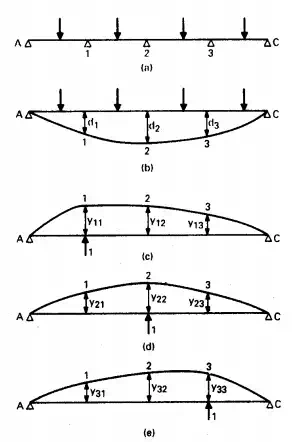
FIGURE 5.59 Determination of reactions of continuous beam AC: (a) Loaded beam with supports at points 1, 2, and 3. (b) Deflection of beam when supports are removed. (c) to (e) Deflections when a unit load is applied successively at points 1, 2, and 3.
Hence, while the bending moments in a simply supported beam are determined only by the loads and the span, bending moments in a statically indeterminate member are also a function of the geometry, cross-sectional dimensions, and modulus of elasticity.
Sign Convention
For computation of end moments in continuous beams and frames, the following sign convention is most convenient: A moment acting at an end of a member or at a joint is positive if it tends to rotate the joint clockwise, negative if it tends to rotate the joint counter clockwise.
Similarly, the angular rotation at the end of a member is positive if in a clockwise direction, negative if counter clockwise. Thus, a positive end moment produces a positive end rotation in a simple beam. For ease in visualizing the shape of the elastic curve under the action of loads and end moments, bending-moment diagrams should be plotted on the tension side of each member. Hence, if an end moment is represented by a curved arrow, the arrow will point in the direction in which the moment is to be plotted.


Comments are closed.