According to Indian Standard IS 800, the slenderness ratio should not exceed the values given in the table below:
| No. | Type of Member | Slenderness ratio |
| 1 | A member carrying compressive loads resulting from dead and superimposed loads. | 180 |
| 2 | A member subjected to compressive loads resulting from wind/earthquake forces provided the deformation of such members does not adversely affect the stress in any part of the structure. | 250 |
| 3 | A member normally carrying tension but subjected to reversal of stress due to wind or earthquake forces. | 350 |
| 4 | Tension member (other than pre-tensioned member) | 400 |
ANGLE STRUTS
Single angle discontinuous struts connected by a single rivet or bolt may be designed for axial load only provided the compressive stress does not exceed  . The value of
 ![]() can be determined on the basis that the effective length l of the strut is from centre-to-centre of inter-section at each end and r is the minimum radius of gyration. In no case, the
can be determined on the basis that the effective length l of the strut is from centre-to-centre of inter-section at each end and r is the minimum radius of gyration. In no case, the ![]() ratio for single angle struts should exceed 180. If a single discontinuous strut is connected by a weld or by two or more rivets or bolts in line along the angle at each end, it may be designed for axial load only provided the compression stress does not exceed
ratio for single angle struts should exceed 180. If a single discontinuous strut is connected by a weld or by two or more rivets or bolts in line along the angle at each end, it may be designed for axial load only provided the compression stress does not exceed ![]() arrived at on the basis that l is taken as 0.85 times the length of the strut, centre to centre at each end and r is the minimum radius of gyration.
arrived at on the basis that l is taken as 0.85 times the length of the strut, centre to centre at each end and r is the minimum radius of gyration.
For double angle struts which are discontinuous, back to back connected to both sides of the gusset or section by not less than two bolts or rivets in line along the angles at each end or by equivalent welding, the load may be regarded as applied axially. The effective length l in the plane of end gusset could be taken between 0.7 and 0.85 times the distance between the intersection depending on the restraint provided, the plane perpendicular to that of the end gusset, the effective length should be taken as equal to the distance between centers of intersections. The calculated average compressive stress should not exceed values of ![]() obtained for the appropriate slenderness ratios. The angles should be connected together with tack rivets or welds at intervals along their lengths.
obtained for the appropriate slenderness ratios. The angles should be connected together with tack rivets or welds at intervals along their lengths.
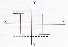
COMPRESSION MEMBERS COMPOSED OF BACK-TO-BACK COMPONENTS
A compression member composed of two angles, channels or tees, back to back, in contact or separated by a small distance should be connected together by riveting, bolting or welding so that the slenderness ratio of each member between the connections is not greater than 40 nor greater than 0.60 times the most unfavourable slenderness ratio of the strut as a whole. In no case, the spacing of tacking rivets in a line exceed 600mm for such members.
For other types of built-up compression members, where cover plates are used, the pitch of tacking rivets should not exceed 32t or 300mm, whichever is less, where t is the thickness of the thinner outside plate. Where plates are exposed to bad weather conditions, the pitch should not exceed 16 t or 200mm whichever is less.
The rivets, welds and bolts in these connections should be sufficient to carry the shear force and bending moments, if any, specified for battened struts. The diameter of the connecting rivets should not be less than the minimum diameter given in the table below:
| Thickness of member | Minimum diameter of rivets |
| Upto 10mm | 16mm |
| Over 10mm upto 16mm | 20mm |
| Over 16mm | 22 mm |
Solid packing or washers should be used for riveting, bolting, where the members are separated back to back.
The end struts should be connected together with not less than two rivets or bolts or their equivalent in welding and there should be not less than two additional connections spaced equidistant in the length of the strut.
A minimum of two rivet or bolts should be used in each connection, one on line of each gauge mark, where the legs of the connected angles or tables of the connected tees are 125mm wide or over, or where the webs of channel are 150mm wide or over.
LACINGS AND BATTENS FOR BUILT-UP COMPRESSION MEMBERS
As per Indian Standard, IS 800-1984, the following specifications are used for the design of lacing and batten plates.
In a built-up section, the different components are connected together so that they act as a single column. Lacing is generally preferred in case of eccentric loads. Battening is normally used for axially loaded columns and in sections where the components are not far apart. Flat bars are generally used for lacing. Angles, channels and tubular sections are also used for lacing of very heavily columns. Plates are used for battens.
Lacings
A lacing system should generally conform to the following requirements:
- The compression member comprising two main components laced and tied should, where practicable, have a radius of gyration about the axis perpendicular to the plane of lacing not less than the radius of gyration at right angles to that axis.
- The lacing system should not be varied throughout the length of the strut as far as practicable.
- Cross (except tie plates) should not be provided along the length of the column with lacing system, unless all forces resulting from deformation of column members are calculated and provided for in the lacing and its fastening.
- The single-laced systems on opposite sides of the main components should preferably be in the same direction so that one system is the shadow of the other.
- Laced compression members should be provided with tie plates at the ends of the lacing system and at points where the lacing system are interrupted. The tie plates should be designed by the same method as followed for battens.


Comments are closed.