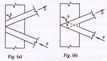
The angle of inclination of the lacing with the longitudinal axis of the column should be between ![]() to
to ![]() .
.
- The slenderness ratio
 of the lacing bars should not exceed 145.
 - The effective length
 of the lacing bar should be according to the table given below:
| No. | Type of lacing | Effective length, |
| 1 | Single lacing, riveted at ends | Length between inner end rivets on lacing bar. |
| 2 | Double lacing, riveted at ends | 0.7 times the length between end rivets on lacing bars. |
| 3 | Welded lacing | 0.7 times the distance between inner ends or effective lengths of welds at ends. |
- For riveted or welded lacing system,
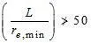 or 0.7 times maximum slenderness ratio of the compression member as a whole, whichever is less.
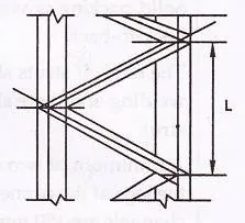
Here, L = distance between the centers of connections of the lattice bars, and
![]() = the minimum radius of gyration of the components of the compression member.
= the minimum radius of gyration of the components of the compression member.
- Minimum width of lacing bars in riveted connection should be according to the Table given below:
| Nominal rivet diameter (mm) | 22 | 20 | 18 | 16 |
| Width of lacing bars (mm) | 65 | 60 | 55 | 50 |
- Minimum thickness of lacing bars:
 , for single lacing;
![]() , for double lacing
, for double lacing
Where ![]() = length between inner end rivets.
= length between inner end rivets.
- The lacing of compression members should be designed to resist a transverse shear, V=2.5 percent of the axial force in the member. The shear is divided equally among all transverse lacing systems in parallel planes. The lacing system should also be designed to resist additional shear due to bending if the compression member carries bending due to eccentric load, applied end moments, and / or lateral loading.
- The riveted connections may be made in two ways, as shown in the figure (a) and (b).
WELDED CONNECTION
Lap Joint – Overlap should not be less than ¼ times thickness of bar or member, whichever is less.
Butt Joint – Full penetration butt weld or fillet weld on each side, lacing bar should be placed opposite to flange or stiffening component of main member.
BATTENS
Compression members composed of two main components battened should preferably have these components of the same cross-section and symmetrically disposed about their X – X axis.
The battens should be placed opposite to each-other at each end of the member and at points where the member is stayed in its length, and should as far as practicable, be spaced and proportioned uniformly throughout.
The effective length of columns should be increased by 10 percent.
Design Details of Battens
- Spacing of batten C, from centre-to-centre of end fastening should be such that the slenderness ratio of the lesser main component,
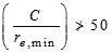 or 0.7 times the slenderness ratio of the compression member as a whole about X – X axis (parallel to battens) whichever is less.
 - Effective depth of battens, d shall be taken as distance between end rivets or end welds.
 for intermediate batten
d > a, for end batten
d > 2b , for any batten
where d = effective depth of batten
a = centroidal distance of members
b = width of members in the plane of battens.
- Thickness of battens,

Where, ![]() = distance between the innermost connecting line of rivets or welds.
= distance between the innermost connecting line of rivets or welds.
DESIGN OF BATTENS
Battens should be designed to carry bending moment and shear arising from a transverse shear,

Where P = total axial load in the compression member.
Transverse shear V is divided equally between the parallel planes of battens. Battens and their connections to main components resist simultaneously a longitudinal shear.

and , moment 
due to transverse shear V.
where, C = spacing of battens
N= number of parallel planes of battens
S= minimum transverse distance between centroid of rivet group or welding.
The end connections should also be designed to resist the longitudinal shear force ![]() and the moment M.
and the moment M.
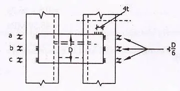
For welded connection
- Lap < 4t
- Total length of weld at edge of batten < D/2
a + b+ c < D/2
let t = thickness of batten
Length of continuous weld at each edge of batten < 1/3 of total length required.
Return weld along transverse axis of the column < 4t
Where, t and D are the thickness and overall depth of battens, respectively.


Comments are closed.